Do you have a question about the Ecoflam MAX 1 and is the answer not in the manual?
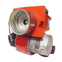
Details burner output, fuel consumption, hydraulic system, and fuel type.
Covers control box, air regulation, flame monitor, ignition, pump, motor, voltage, and power.
Specifies weight, IP rating, sound level, and ambient temperature ranges.
Explains how burner output relates to combustion chamber pressure.
Advises considering boiler efficiency when selecting a burner.
Provides the formula to calculate burner output based on boiler output and efficiency.
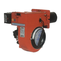
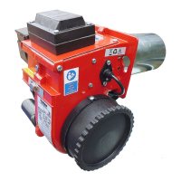
Provides detailed dimensional data for MAX 1, 4, 8, and 12 models.
Lists dimensions (X, Y, Z) and weight (Kg) for packaging.
Describes the pre-heating sequence for version R burners.
Details the sequence of operations during normal burner function.
Explains the process of controlled shutdown initiated by the boiler thermostat.
Outlines the conditions that trigger a safety shutdown and its indication.
Explains the function and microprocessor control of the E-BCU unit.
Describes how to lock and unlock the control unit using the reset button.
Illustrates the electrical supply and operational sequence of the control unit.
Identifies the SUNTEC and DANFOSS oil pumps used.
Shows connections for a two-pipe system with bleed filter.
Explains modifications for a one-pipe system supply circuit.
Guides on how to fix the burner to the boiler flange and secure it.
Advises on the correct placement of the filter and hose routing.
Details burner pipe insertion depth and brickwork requirements.
Recommends avoiding right-angled connectors for noise reduction.
States that installation must be done by an authorized specialist.
Emphasizes checking electrode position after nozzle replacement.
Describes the plug-in connection and the 7-pin connector.
Lists essential checks before starting the burner for the first time.
Provides length tables for feeding lines with Suntec pumps.
Offers length tables for feeding lines with Suntec pumps.
Provides length tables for feeding lines with Danfoss pumps.
Offers length tables for feeding lines with Danfoss pumps.
Presents a table with nozzle, pump, output, firing head, and air damper settings.
Explains how to adjust the air damper using the screw.
Details how to adjust the firing head using an Allen key.
Guides on adjusting oil pressure via the regulator to set burner output.
Advises on modifying combustion head position for optimal values.
Explains how to check negative pressure and its importance.
Provides instructions for cleaning the pump filter.
Advises on regular checks of flue gas temperature.
Describes three positions for fixing the burner for maintenance.
Guides on positioning the motor and blower wheel during replacement.
Details the process for replacing the nozzle and cleaning.
Outlines initial checks and a table for diagnosing faults and remedies.
Lists faults, their causes, and recommended remedies for burner malfunctions.
Shows the wiring diagram for the control box and its components.
Labels various electrical components in the diagram.
Illustrates and lists spare parts for the MAX 1 model.
Illustrates and lists spare parts for MAX 4, 8, and 12 models.
Provides a detailed table of spare parts with descriptions and codes for MAX 1.
Lists spare parts with codes for MAX 4, MAX 8, and MAX 12 models.







 Loading...