3 Structure
3.1
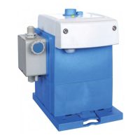
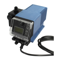
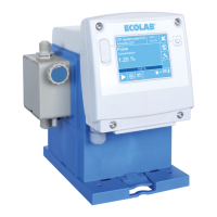
Metering pump - ‘EcoPro’ / ‘EcoUp’
1
2
3
4
5
6
7
1
2
3
4
5
6
7
8
9
18
20
20
14
16
15
13
12
11
14
16
15
13
12
11
10 10
17
19
18
Fig. 1: Construction of ‘EcoPro’ / ‘EcoUp’
1 Rotary knob for adjusting the dosage rate
2 Locking mechanism for fixing the rotary button in place
3 LED - Alarm signal, colour: red flashing
4 LED - Operating status/dosing mode:
ready for operation = green illuminated,
operation (pump running) = flashing yellow
,
dosing mode: viscosity low (left LED)
5 LED - Operating status/dosing mode:
ready for operation = green illuminated,
operation (pump running) = flashing yellow,
dosing mode: viscosity high (right LED)
6 On/off switch
7 Test button
8 Mode LED (EcoUp only)
9 Mode change-over key (EcoUp only)
10 Control panel
11 Rotating control unit
12 Pressure connection / pressure valve
13 Pump head
14 Suction connection / suction valve
15 Air bleed connection
16 Cable bushing for mains cable/power supply
17 Cable bushing for connection: Alarm or dosage rate
output (EcoUp only)
18 Cable bushing for connection: Pulse (EcoUp only) or
enable input
19 Cable bushing for connection: Level input (EcoUp only)
20 Position of type plate
To enable the extension of cable bushings that have not yet been installed, the
pump is provided with corresponding cable glands (M12 x 1.5) (
Fig. 1 , 17 or
18 ).
Permissible external cable diameters for connecting the inputs/outputs:
– AD Ø = 5.1–5.7 mm
Permissible cables:
– LIYY 4x 0.5; LIYY 5 x 0.34; LYCY 2 x 0.34; Ölflex 4 x 0.5
Structure
13 10240750 Ver. 4-11.2023