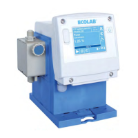
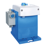
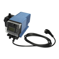
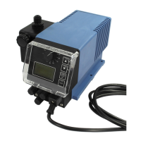
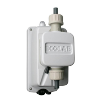
4.3.1 Electrical installation of ‘EcoPro’
Fig. 8: Electrical installation of ‘EcoPro’
1 Housing screw
2 Terminal cover
3 "Electrical connection" front view
4 Cable connections
L1 Mains phase (live conductor)
N Neutral (earth)
8 Enable signal, earth (GND)
9 Enable signal, signal input
1. Remove both housing screws (
Fig. 8 , 1 ).
2. Remove the terminal cover ( 2 ).
3. For connecting the enable input, fit the cable union ( 4 ) from the pump accessories
pack.
4. Route the connector lines through the threaded cable union.
5. Complete the electrical installation.
6. After the electrical installation has been completed, fit the terminal cover back onto
the housing.
NOTICE!
The seal must be free of impurities to ensure the tightness of the system.
7. T
ighten housing screws by hand (approx. 1 Nm).
Assembly and connection
21 10240750 Ver. 4-11.2023
 Loading...
