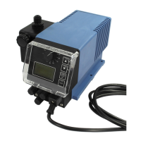
4.3.3 Electrical installation of ‘EcoAdd
’
Fig. 11: Electrical installation of ‘EcoAdd’
1 Front cover screw
2 Front cover / display cover
3 Cable grommets
4 Seal
5
Terminal board
Ä
‘Terminal assignment’ on page 25
1. Remove all four housing screws (
Fig. 11 , 1 ).
2. Remove the front cover ( 2 ).
3. Route the connector lines through the cable grommets ( 3 ).
The maximum cable diameter is described in the EcoAdd operating
instructions.
Ä
‘Available instructions’ on page 3
4. Complete the electrical installation.
5. After the electrical installation has been completed, fit the cover back onto the
housing.
NOTICE!
The seal must be free of impurities to ensure the tightness of the system.
6. T
ighten housing screws by hand (approx. 1 Nm).
CAUTION!
The various connection options are described in detail in the EcoAdd operating
instructions (MAN046939).
Ä
‘Available instructions’ on page 3
Assembly and connection
2410240750 Ver. 4-11.2023