4.3.2 Electrical installation of ‘EcoUp’
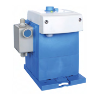
Fig. 9: Electrical installation of ‘EcoUp’
1 Housing screw
2 Terminal cover
3 Cable connections
4 Dosage rates or alarm output
5 Pulse or enable input
6 Level input
7 Seal
8
Terminal board
Ä
‘Terminal assignment’ on page 23
1. Remove both housing screws (
Fig. 9 , 1 ).
2. Remove the terminal cover ( 2 ).
3. T
o connect the dosage rate output or alarm output, mount the cable union ( 3 ) from
the pump accessories pack at the appropriate location ( 4 ), feed through the cable,
tighten the threaded union and connect the cable wires according to the terminal
diagram.
4. T
o connect to the pulse input or enable input, pass the cable through the
corresponding cable union ( 5 ), tighten the threaded union and connect the cable
wires according to the terminal diagram.
5. Connect the connection for the level input to the socket ( 6 ) provided for this
purpose.
6. After the electrical installation has been completed, fit the terminal cover ( 2 ) back
onto the housing.
NOTICE!
The seal must be free of impurities to ensure the tightness of the system.
7. T
ighten housing screws by hand (approx. 1 Nm).
CAUTION!
The various connection options are described in detail in the EcoUp operating
instructions, MAN049656 (see
Ä
Chapter 1.1 ‘Notes on the operating
instructions’ on page 2 ).
Assembly and connection
2210240750 Ver. 4-11.2023
 Loading...