Installation & Operation Manual Proven Quality since 1892
ECON actuator Fig. 7907, type ELA80 – 3000 www.eriks.com
Rev.23 – August, 2023 34
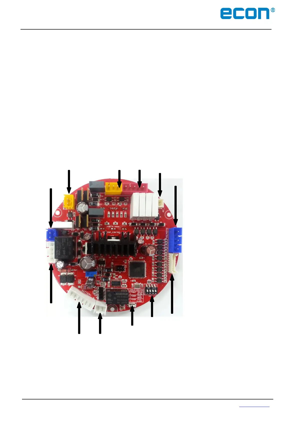
5.4 PCB Layout
1. DC Power Connector
2. Battery Connector
3. Battery Switch Connector
4. Limits / Torque Signal Connector
5. Remote Control Signal
6. Status Contactor
7. PCU Signal
8. Motor Connector
9. AC Power Monitor (option)
10. DIP Switches
11. Power check
12. Battery active switch
Note: If the actuator does not work on battery power, despite of a fully charged battery and a jumper has been
placed on terminal strip connection number 1 and number 4, please press the battery active switch (12).