Do you have a question about the Econ ELA100 and is the answer not in the manual?
Provides an overview of the manual's scope and content for ELA-series electric actuators.
Details essential safety precautions for installing, operating, and maintaining ELA-series electric actuators.
Explains how to identify the actuator and its key information from the nameplate.
Details the specific markings and information found on the actuator's nameplate for identification.
Provides general details about ELA-series actuators, including technical data, options, duty cycle, and manual override.
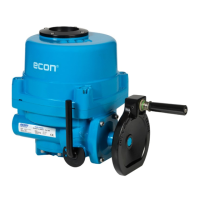
Identifies and illustrates external components for ELA80-1200 and ELA2000-3000 models.
Shows and labels internal components for ELA80-3000 actuator models.
Covers essential checks before installation, including power supply, general service, and explosive atmosphere precautions.
Explains mounting procedures, ISO 5211 details, and drive bushing options.
Step-by-step instructions for setting the fully open and fully closed limit switches using cams.
Information on torque switches that prevent damage under overload conditions; factory set.
Instructions on how to reconfigure the actuator for counter-clockwise rotation to close.
Procedure for adjusting the mechanical stops to define the actuator's travel limits.
Guide for recalibrating the potentiometer for accurate position feedback.
Details the CPT for providing a 4-20mA output signal indicating actuator position and its calibration.
Information on PCU-A, PCU-D, PCU-EB for modulating control, including LED indications and function settings.
Describes the AC/DC Multi-Board, its terminal blocks, and power input switch settings.
Overview of the Rechargeable Battery Pack (RBP) and its operation in Local or Remote mode.
Lists features of the RBP, including operation during power failure and DIP switch functions.
Details the electrical specifications, temperature, humidity, and actuator functions via DIP switches for the RBP.
Illustrates and labels the components on the Printed Circuit Board (PCB) for the RBP.
Explains the different operating modes (Stop, Local, Remote, Battery) and LED status indications.
Describes the ProfiBus controller, its features, and communication specifications.
Explains the ModBus-RTU Slave Module (MBRSM) and its role in communication.
Covers electrical connections, wiring precautions, and preliminary tests for actuator operation.
Provides guidelines and warnings for performing routine maintenance on the actuator.
Lists the recommended tools required for maintenance and troubleshooting procedures.
Troubleshooting steps for optional equipment like Potentiometers and Current Position Transmitters.
Illustrates internal and external grounding procedures for ELA80 and ELA100 actuators.
Illustrates internal and external grounding procedures for ELA150 to ELA3000 actuators.
| Brand | Econ |
|---|---|
| Model | ELA100 |
| Category | Controller |
| Language | English |