Do you have a question about the EcoWater Series 2000 and is the answer not in the manual?
Steps for installing fittings onto the valve ports for various pipe types.
Instructions on how to safely turn off the water supply before installation.
Guidance for installing a 3-valve bypass system, including soldering and threading.
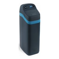
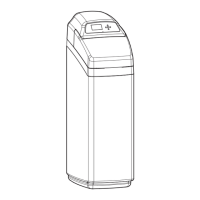
Instructions on positioning the unit, ensuring a level surface with plywood if needed.
Steps to measure, cut, and assemble piping from the bypass valves to the unit.
Detailed instructions for connecting plumbing using soldered copper, threaded pipe, or CPVC plastic.
Instructions for connecting and routing the drain hose, including air gap requirements.
How to connect the transformer to the unit and a grounded electrical outlet.
Procedure to test the installed plumbing for leaks and air purging.
How to initiate a recharge cycle to draw sanitizing bleach through the unit.
Steps to connect the wire harness, valve motor leadwire to the timer.
Step-by-step guide to set the current time and day of the week on the timer.
Guide to setting specific days and times for the unit's regeneration cycles.
Overview of the unit's resin bed, ion-exchange process, and regeneration concept.
Explains the fill cycle where water is added to the brine tank to create brine.
Explains the brining and brine rinse cycles, including brine draw and mineral release.
Details the backwash cycle, its purpose, and water flow.
Explains the fast rinse cycle and how it prepares the resin bed for service.
Instructions for cleaning the nozzle and venturi to ensure proper suction.
Guides for initial checks and troubleshooting using electronic diagnostics.
Procedures to advance the unit through regeneration cycles for operational checks.
A checklist of common initial checks to perform before advanced troubleshooting.
Explains the unit's self-diagnostic function and error codes.
Steps to clear error codes from the faceplate display after correcting a defect.
| Brand | EcoWater |
|---|---|
| Model | Series 2000 |
| Category | Water System |
| Language | English |