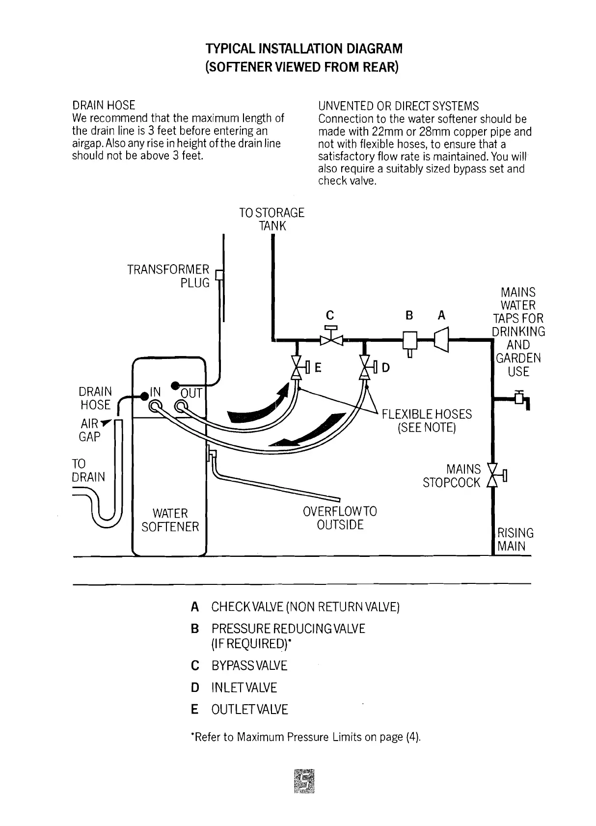
TYPICAL INSTALLATION DIAGRAM
(SOFTENER
VIEWED
FROM
REAR)
DRAIN HOSE
UNVENTED OR DIRECT SYSTEMS
We recommend that the
maximurr~ length of
Connection to the water softener should be
the drain line is
3
feet before entering an
made with 22mm or 28mm copper pipe and
airgap.Also any rise in height of the drain line
not with flexible hoses, to ensure 'that a
should not be above
3
feet.
satisfactory flow rate is maintained. You will
also require a suitably sized bypass set and
check valve.
TO STORAGE
TAN
K
TRANSFORMER
MAIIUS
WATER
B
A
TAPS FOR
A
CHECKVALVE (NOIU RETURN VALVE)
B
PRESSURE REDUCINGVALVE
(IF REQUIRED)*
C
BYPASS VALVE
E
OUTLETVALVE
'Refer to Maximum Pressure Limits on page
(4).



 To Next Page