22
Installing the Motherboard
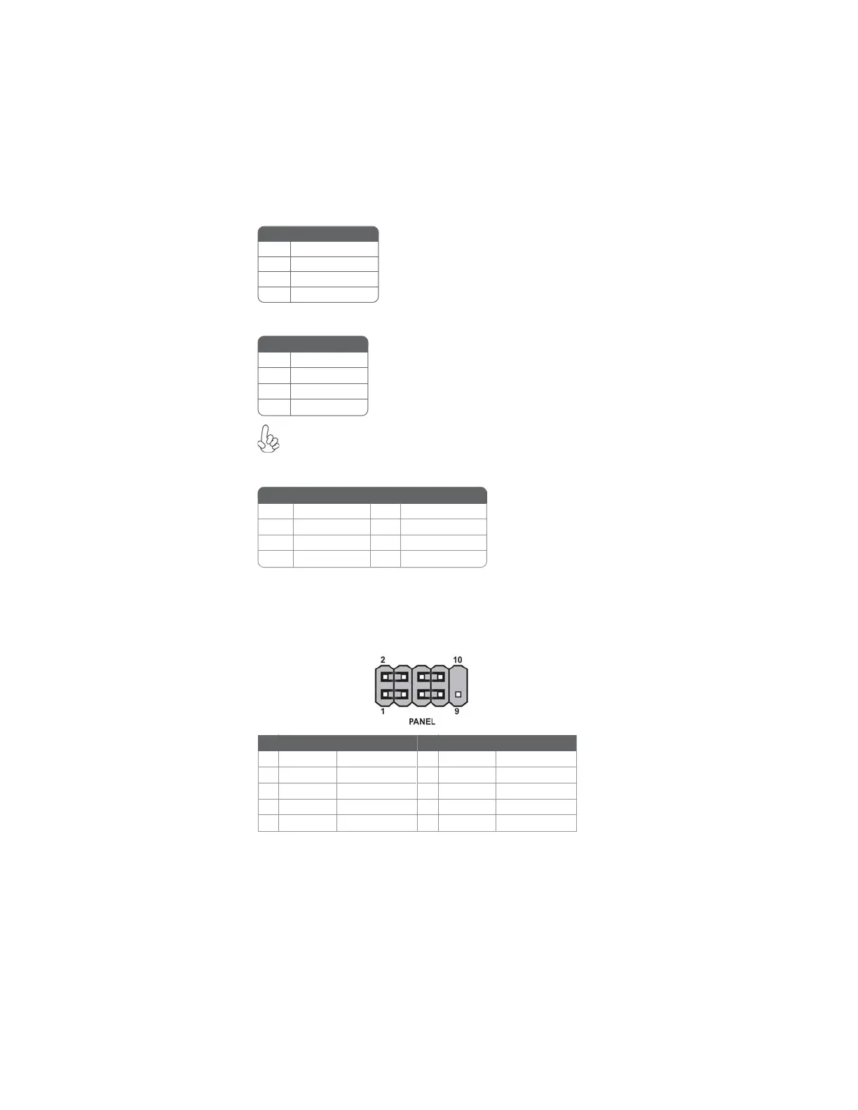
Front Panel Header
The front panel header (PANEL) provides a standard set of switch and LED headers
commonly found on FULL ATX, ATX or Micro ATX cases. Refer to the table below
for information:
ATX4P: Auxiliary Power Connector for Graphics Interface
Pin Signal Name
4 +12V
3 GND
2 GND
1 NC
Make sure to connect a 4-pin ATX power cable to ATX4P; otherwise,
the system will be unstable.
ATX12V: ATX 12V Power Connector
Pin Signal Name
4 Ground
3 Ground
2 Ground
1 Ground
Pin Signal Name
5 +12V
6 +12V
7 +12V
8 +12V
SPK: Internal speaker
Pin Signal Name
1 VCC
2 Key
3 NC
4 Signal
Pin Signal Function Pin Signal Function
1 HD_LED_P Hard disk LED (+)
2 FP PWR/SLP *MSG LED (+)
3 HD_LED_N Hard disk LED (-)
5 RST_SW_N Reset Switch (-)
7 RST_SW_P Reset Switch (+)
9 RSVD Reserved
4 FP PWR/SLP *MSG LED (-)
6 PWR_SW_P Power Switch (+)
8 PWR_SW_N Power Switch (-)
10 Key No pin
* MSG LED (dual color or single color)
 Loading...