38
6. When monitoring and a (N.O.) contact closure required, connect to the “Over” contacts on block
J5 (J5-1 & J5-2).
a. If a LOW Nitrogen (N
2
)/HIGH Oxygen (O
2
) percentage alarm is desired, select the
corresponding oxygen concentration level using dip 2, 3 or 4 of Switch 1 to energize the
“OVER” relay output.
b. Dip 2 of Switch 1 (5%) is recommended.
7. When monitoring and an analog output is required, connect positive lead to AOUT+ (J4-1) and
negative lead to AOUT– (J4-2).
a. 4-20mA Output - Turn on Dip 1 of Switch 2 to 4-20mA.
b. 0-5VDC or 0-10VDC Output:
i. Turn on Dip 1 of Switch 2 to V
ii. Use Dip 2 of Switch 2 to select 5V (for 0-5VDC) or 10V (for 0-10VDC).
8. If RS-485 remote control/monitoring is desired, connect RS-485 leads to D+ (J4-4), D- (J4-5) and
DGND (J4-6).
Alarm Bypass While Nitrogen Inerting Feature
The “Over” contacts can be bypassed from transmitting a low nitrogen signal to the building monitoring
system during the fourteen (14) day nitrogen inerting process when the SGA-1 is used in conjunction with
the PSV-D/DE SMART Vent.
1. Connect the spare normally closed (N.C.) contacts (Terminals 8 and 11) in the PSV-D/DE SMART Vent
Controller with the normally open (N.O.) contacts of the SGA-1 (Terminals J5-1 and J5-2).
2. Connect the output of the SGA-1 and PSV-D/DE to the building monitoring system.
3. Connect the building monitoring system’s end-of-line supervision device (if needed)
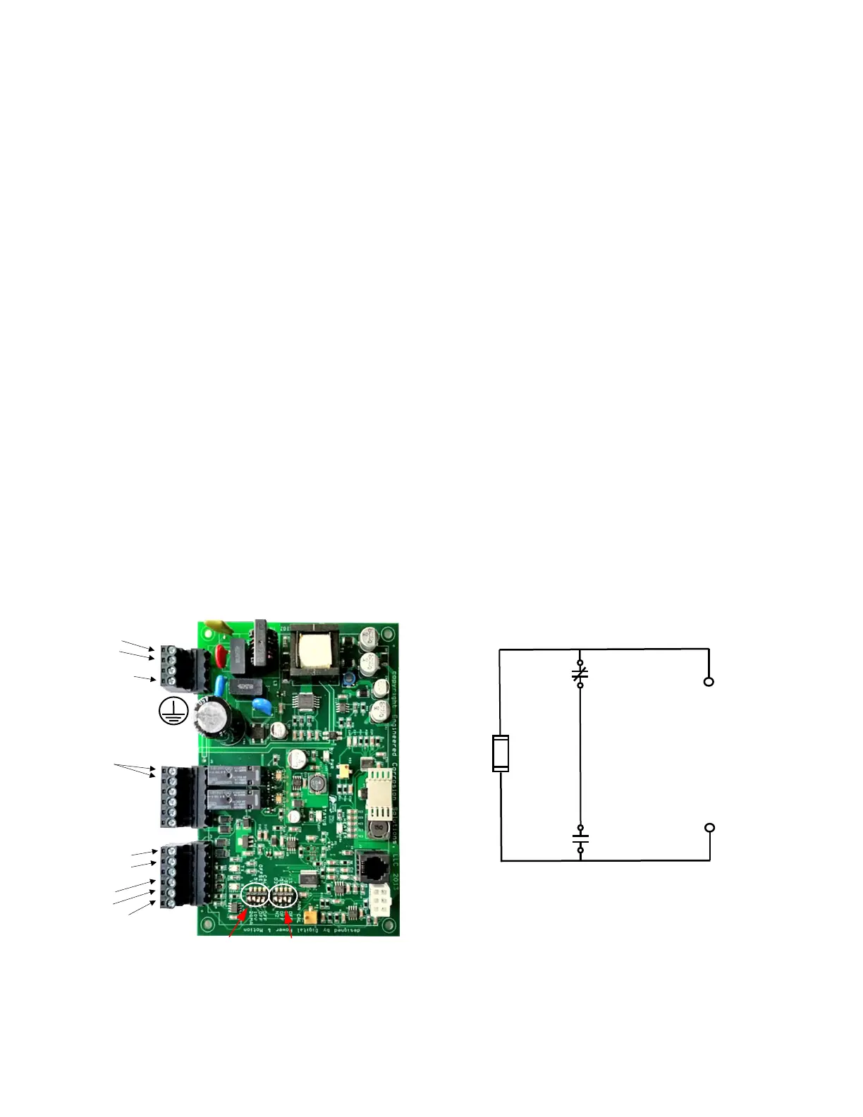
PC Board Wiring Diagram Inerting Bypass Wiring Diagram
 Loading...