10
Installing the Motherboard
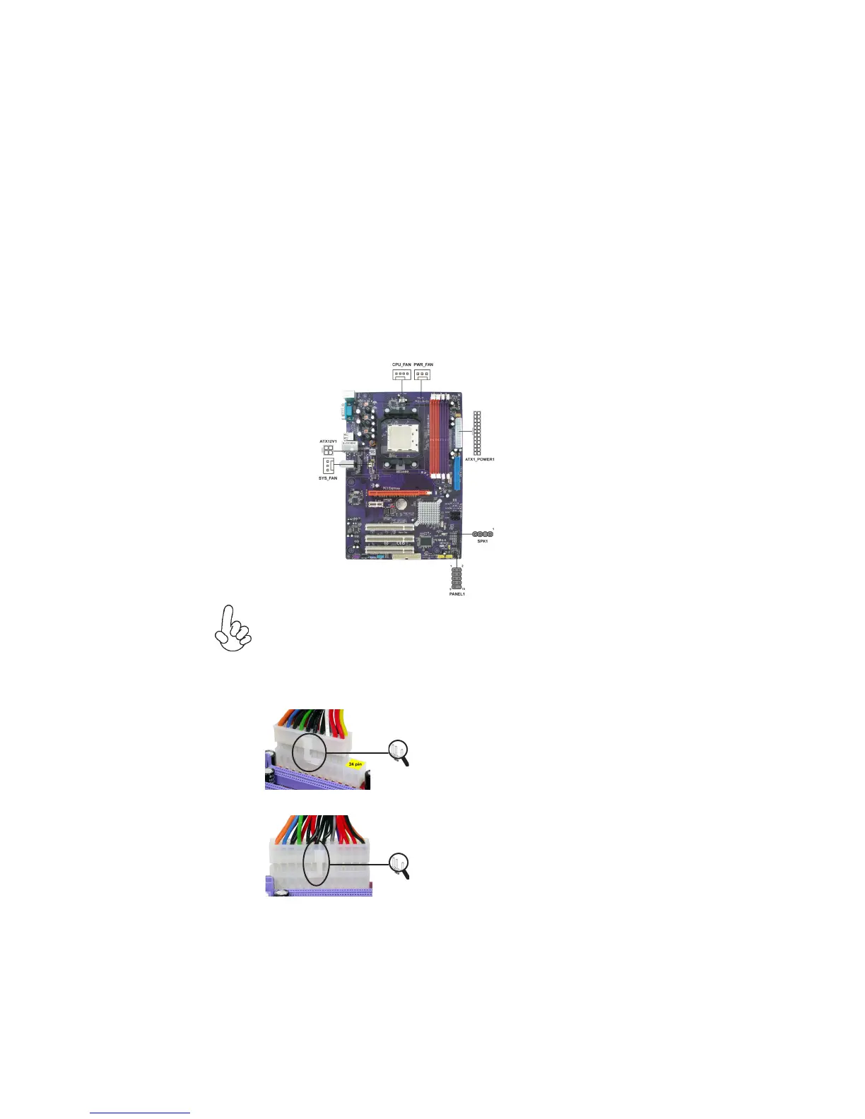
Connecting Case Components
After you have installed the motherboard into a case, you can begin connecting the
motherboard components. Refer to the following:
1 Connect the CPU cooling fan cable to CPU_FAN.
2 Connect the power cooling fan connector to PWR_FAN (optional).
3 Connect the system cooling fan connector to SYS_FAN.
4 Connect the case speaker cable to SPK1.
5 Connect the standard power supply connector to ATX_POWER1.
6 Connect the auxiliary case power supply connector to ATX12V1.
7 Connect the case switches and indicator LEDs to the PANEL1.
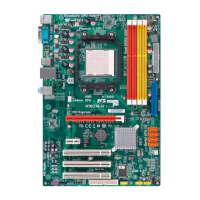
Connecting 20/24-pin power cable
Users please note that the 20-pin and 24-pin power cables can both be con-
nected to the ATX_POWER1 connector. With the 20-pin power cable, just
align the 20-pin power cable with the pin 1 of the ATX_POWER1 connector.
However, using 20-pin power cable may cause the system to become unbootable
or unstable because of insufficient electricity. A minimum power of 300W is
recommended for a fully-configured system.
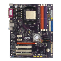
20-pin power cable
24-pin power cable
With ATX v1.x power supply, users please
note that when installing 20-pin power cable,
the latche of power cable clings to the left
side of the ATX_POWER1 connector latch,
just as the picture shows.
With ATX v2.x power supply, users please
note that when installing 24-pin power cable,
the latches of power cable clings to the right
side of the ATX_POWER1 connector latch.