PRODUCT SAFETY SOLUTIONS
© 2012 Educated Design & Development, Inc. All rights reserved. Rev B: February, 2012 Page 13 of 19
OPERATING INSTRUCTIONS: (Continued)
grounding lead. Remember, the reason to isolate the product is to simulate the worst-case scenario of the
product not being reliably grounded and the human body being subjected to the entire leakage current.
If you are at the installation site and you can verify that the product is reliably grounded, you may not be
concerned with the overall leakage current with the product completely isolated. Rather, you may only want
to know if there is extraneous leakage current from an operator surface, which could present a shock
hazard. Similarly, you may want to measure the current in the main grounding conductor after servicing the
product. In order to make such measurement, refer to the previous instructions for Surface-to-Surface,
Surface to Reference, and D.U.T. grounding conductor.
WARNING: WHEN TESTING A PRODUCT THAT CANNOT BE ISOLATED, ALWAYS SET THE METER
REFERENCE SWITCH TO GROUND. SETTINGS OTHER THAN GROUND, WHEN THE DEVICE
UNDER TEST IS NOT ISOLATED, CAN RESULT IN LINE VOLTAGE BEING APPLIED ACROSS THE
METER MEASUREMENT CIRCUIT. THE RESULT IS EXCESSIVE CURRENT THROUGH THE METER
THAT CAN CAUSE THE METER FUSE TO BLOW.
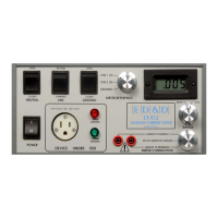
THEORY OF OPERATION:
This section of the manual contains a description of the circuitry used in the LT-952. During this discussion,
please refer to the Block Diagram located following this section.
The LT-952 is composed of 3 major sections. The first is the high current handling switching section. The
second is the meter measurement section, and the third is the low Voltage power supply.
AC Current Switching Circuit
The AC Current Switch section consists of the rear panel incoming power connector, and both front and
rear panel D.U.T. outlets. This section also contains the Test Condition, Ground Switching, and 120 Volt
Disconnect blocks.
Test Condition Simulator
This section is composed of two switches. The first, a SPST type, is used to simulate an open neutral
condition. The second relay, a DPDT type, is used to physically reverse the hot and neutral wires
connected to the product under test.
Ground Switching
A momentary SPDT switch is used to perform the ground switching function. In the normally closed
position, the ground from the incoming power line is connected to the front and rear panel output
receptacles. When the switch is toggled OPEN, the ground lead of the product under test is routed to the
meter connection selector.