Printed in USA
JWA ©2011
Page 3
PARTS LIST MANUAL
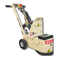
MODELS 2EC AND 2GC
DUAL-DISC CONCRETE FLOOR GRINDERS
TABLE OF CONTENTS
Section Page Number
Safety Messages and General Instructions . . . . . . . . . . . . . . . . . . . . . . . . . . . . . . . 2
How To Order Replacement Parts . . . . . . . . . . . . . . . . . . . . . . . . . . . . . . . . . . . . . . 3
Illustration 1: Main Grouping . . . . . . . . . . . . . . . . . . . . . . . . . . . . . . . . . . . . . . . . . . . 4, 5
Illustration 2: Skirt, Vacuum Port & Water Hook-Up Grouping . . . . . . . . . . . . . . . . . 6, 7
Illustration 3: Multi-Accessory Disc Assembly . . . . . . . . . . . . . . . . . . . . . . . . . . . . . . 8
Illustration 4: Tool Box & Multi-Disc Accessories . . . . . . . . . . . . . . . . . . . . . . . . . . . . 9
Illustration 5: Dyma-Sert™& PCDyma-Sert™Assemblies . . . . . . . . . . . . . . . . . . . . . 10
Illustration 6: Strip-Sert™Assembly . . . . . . . . . . . . . . . . . . . . . . . . . . . . . . . . . . . . . . 11
Illustration 7: Optional Pad Driver Assembly . . . . . . . . . . . . . . . . . . . . . . . . . . . . . . . 12
Illustration 8: Optional Surfacer Disc Assembly . . . . . . . . . . . . . . . . . . . . . . . . . . . . . 13
Illustration 9: Motor & Belt Drive Grouping for 1.5 HP Units . . . . . . . . . . . . . . . . . . . 14, 15
Illustration 10: Motor & Belt Drive Grouping for 2HP 50Hz & 3HP 60Hz Units . . . . . 16, 17
Illustration 11: Engine & Belt Drive Grouping for Honda GXV160 . . . . . . . . . . . . . . 18, 19
Illustration 12: Engine & Belt Drive Grouping for Honda GXV340 . . . . . . . . . . . . . . 20, 21
Illustration 13: Propane Grouping . . . . . . . . . . . . . . . . . . . . . . . . . . . . . . . . . . . . . . . 22, 23
Illustration 14: Optional Weight Blocks & Tray . . . . . . . . . . . . . . . . . . . . . . . . . . . . . 24
Illustration 15: Switch Wiring Diagram for 1.5HP Units . . . . . . . . . . . . . . . . . . . . . . . 25
Illustration 16: Starter Wiring Diagram for 2 & 3 HP Units . . . . . . . . . . . . . . . . . . . . . 26
Illustration 17: Motor Wiring Diagram for 1.5 HP Baldor . . . . . . . . . . . . . . . . . . . . . . 27
Illustration 18: Motor Wiring Diagram for 1.5 HP Leeson . . . . . . . . . . . . . . . . . . . . . 28
Illustration 19: Motor Wiring Diagram for 2 & 3 HP Baldor . . . . . . . . . . . . . . . . . . . . 29
Notes . . . . . . . . . . . . . . . . . . . . . . . . . . . . . . . . . . . . . . . . . . . . . . . . . . . . . . . . . . . . 30, 31
Limited Equipment Warranty of Sale - Terms & Conditions . . . . . . . . . . . . . . . . . . . 32 (Back Page)
I 3 •Ii•J
A Division
of
Equipment Development Company, Inc.
Go to Discount-Equipment.com to order your parts