Page 33
ALR:
Pin 1 +24V +24 V supply voltage
Pin 2 S_R NPN Signal output for "Alarm" = red light on the alarm light
Pin 3 S_Y NPN signal output for "low ink" = yellow light on the alarm light
Pin 4 S_G NPN Signal output for "printer active" = green light on the alarm light
Pin 5 GND Ground / earth
The maximum power drain of all external connectors shall not exceed 1.5 A. The signal outputs
are NPN switched.
If you are using the original edding alarm connection cable, the matching wire colours are on
the open end:
Pin 1 +24V brown
Pin 2 S_R white
Pin 3 S_Y yellow
Pin 4 S_G green
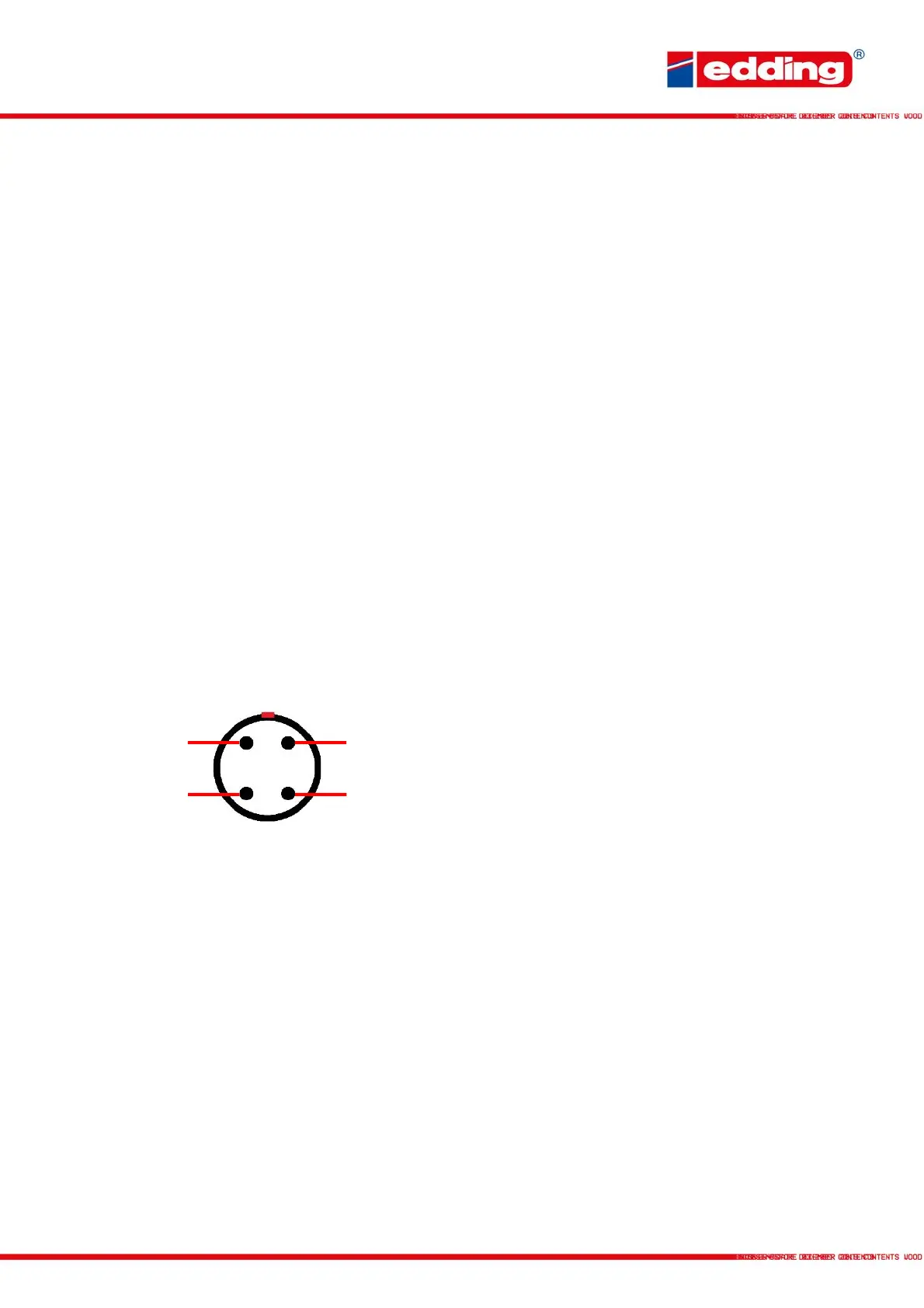
Additional: Edding relay cable - pin assignment and corresponding cable color
Illustration shows the connector view.
Part number: LO-E-I-RK
PIN
ßà
Cable color
Pin 1 ßà white: PNP Signal input: Send a +24V signal for print-go
Pin 2 ßà brown: GND Ground / earth
Pin 3 ßà green: NPN Signal input: Send a GND signal for print-go
Pin 4 ßà yellow: +24V +24 V supply voltage
If possible, please aim to switch potential-free signals. The maximum power drain of all external
connectors shall not exceed 1.5 A. You do not have to set PNP or NPN via the software, both
inputs are leading to similar results. Only do not use them in parallel at the same time. The
inputs are debounced at 3 ms.