Quick Start Guide
– 2 –
Mount the Switch
Ground the Switch
Warning:
For a safe and reliable installation, use only
the accessories and screws provided with the device. Use
of other accessories and screws could result in damage to
the unit. Any damages incurred by using unapproved
accessories are not covered by the warranty.
Avertissement:
Pour une installation sûre et fiable,
utilisez uniquement les accessoires et les vis fournies avec
l’appareil. L’utilisation d’autres accessoires et vis pourrait
endommager l’appareil. Les dommages causés par
l’utilisation d’accessoires non approuvés ne sont pas
couverts par la garantie.
Caution:
Risk of explosion if battery is replaced by an
incorrect type. Dispose of used batteries according to the
manufacturer’s instructions.
Attention:
Risque d’explosion si la batterie est remplacée par
un type incorrect. Éliminez les piles usagées conformément aux
instructions.
Caution:
The switch includes plug-in power supply (PSU) and
fan tray modules that are installed into its chassis. Make sure all
installed modules have a matching airflow direction (front-to-
back or back-to-front).
Attention:
Le commutateur comprend des modules
d’alimentation et de modules de ventilation installés dans son
châssis. Assurez-vous que tous les modules installés ont une
direction d’air adaptée (avant-arrière ou arrière-arrière).
Note:
The switch has the Open Network Install Environment
(ONIE) software installer preloaded on the switch, but no switch
software image. Information about compatible switch software
can be found at
www.edge-core.com.
Note:
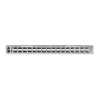
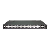
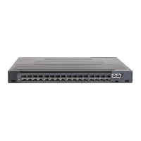
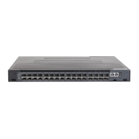
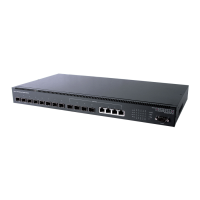
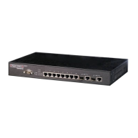
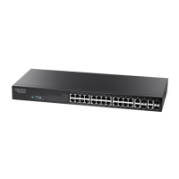
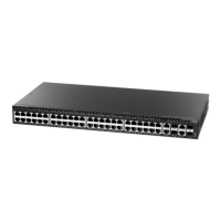
The drawings in this document are for illustration only
and may not match your particular model.
Caution:
This device must be installed in a
telecommunications room or a server room.
Attention:
Cet appareil doit être installé dans une salle de
télécommunication ou une salle de serveur.
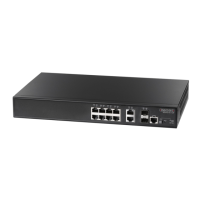
1. Attach the Brackets
Use the included screws to attach the front- and rear-post brackets.
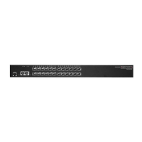
2. Mount the Switch
Mount the switch in the rack and secure it with rack screws.
3. Lock the Rear-Post Brackets
Use the included screws to lock the position of the rear-post brackets.
Verify Rack Ground
Ensure the rack on which the switch is to be mounted is properly
grounded and in compliance with ETSI ETS 300 253. Verify that there is
a good electrical connection to the grounding point on the rack (no
paint or isolating surface treatment).
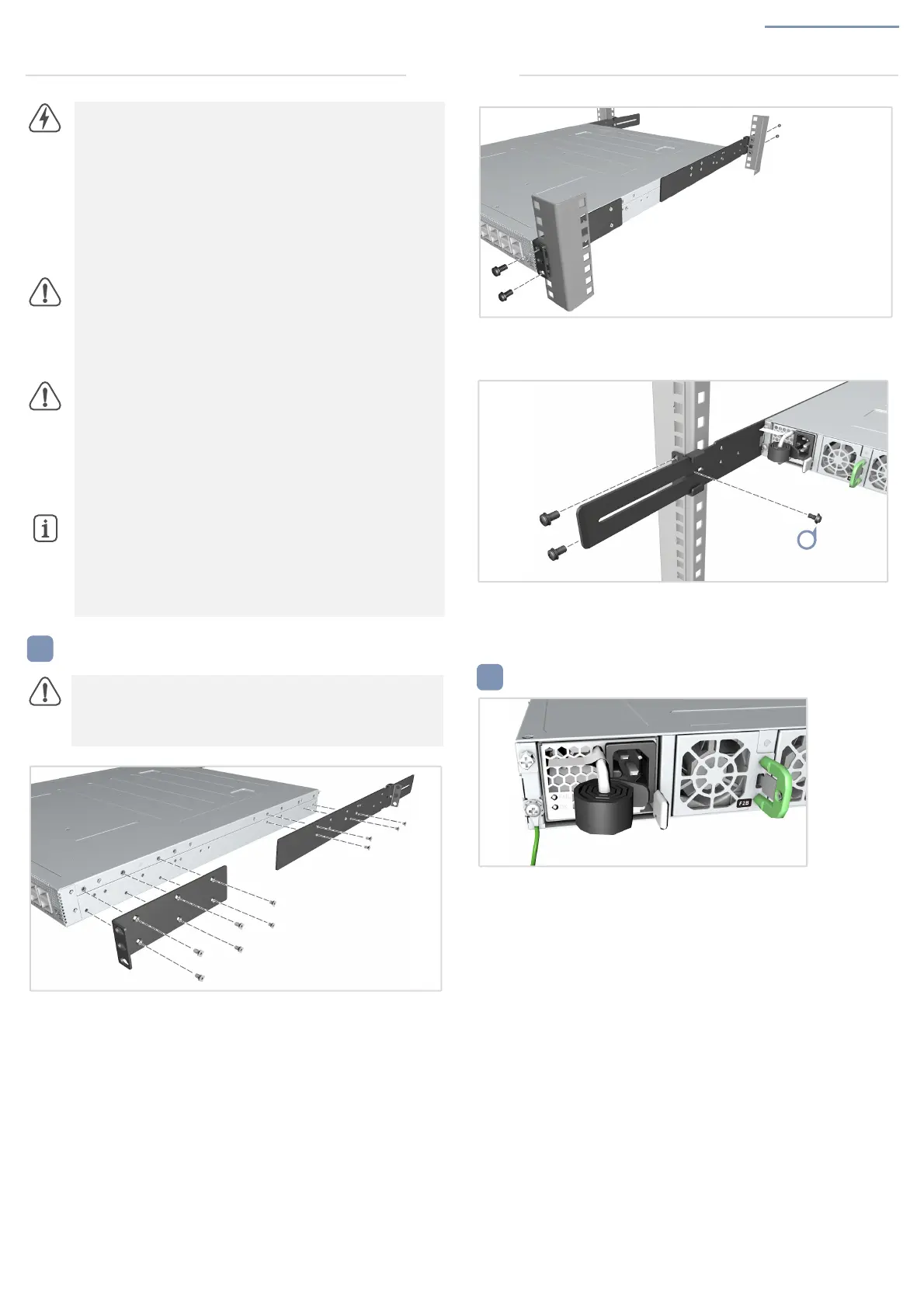
Attach Grounding Wire
Attach a lug (not provided) to a #14 AWG minimum grounding wire
(not provided), and connect it to the grounding point on the switch rear
panel. Then connect the other end of the wire to rack ground.
Installation