en
14
ASSEMBLY
FITTING THE DISK (Fig. 9)
Fix the blade (R) onto the upper ange (F)
making sure that the rotation direction is
correct.Fix the lower ange (E), the cup (D)
and tighten bolt (A) anti-clockwise.Put the pin
provided in the appropriate hole (L) to block the
blade and allow the bolt (A) to be tightened to
2.5 kgm (25 Nm).
WARNING: Collar (see arrows C,
Fig.9) must locate in blade’s mounting
hole.
WARNING: Arrows on the cutting
attachment guard show the correct
direction of rotation of the cutting
tool.
WARNING: Fit the blade protection
(M) p.n. 4196086 as shown (Fig.3)
before transporting or storing the
brush cutter.
CAUTION: Never use the brush cutter
without the cup (D, Fig.9) to avoid
damages to the thread.
WARNING: Never touch or adjust
the blade while the motor is running.
The blade is very sharp, always wear
protective gloves when performing
maintenance.
WARNING: After use the bevel
gear may be very hot, always wear
protective gloves when performing
maintenance.
ASSEMBLING THE HANDLE (Fig. 2)
Fit the handle onto the shaft arm and secure
it using screws (A). The handle position is
calculated depending on the requirements of the
operator.
ASSEMBLING THE BIKE HANDLE (Fig. 4)
- Place the bike handle (A, Fig.4) in the lower
hub (B1).
CAUTION: The bike handle (A) must be
xed onto the hub (B) inside the two notches
(C) indicated on the bike handle.
- Place the upper hub (B2) in position and tighten
the 4 screws (D), without nally tighten yet.
- Line up the handlebar at a right angle to the
drive tube.
- Tighten down the screws (D) rmly.
MOUNTING THE CONTROL HANDLES (Fig. 6)
- Loosen the screw (G, Fig.6). The nut (H)
remains in the control handle (L).
- Push the control handle (L) (throttle trigger M
must point toward the gearbox) onto the bike
handle (N) so that the holes (P) line up.
- Insert screw (G) and tighten down rmly.
WARNING: Make sure that all
components are connected properly
and all screws tightened.
PREPARING TO WORK
HARNESS (4S-4T, Fig. 1)
Correct adjustment of the harness permits the
brush cutter to be properly balanced and at an
appropriate height from the ground (Fig. 10).
- Put on the single harness.
- Hook the brush cutter to the harness using the
hook (A, Fig. 11-12).
- Position the hook (B, Fig. 11-12) to obtain the
best brush cutter balance.
- Position the buckle (C, Fig. 13) to obtain the
correct brush cutter height.
WARNING! – When using wood-
cutting blades (22-60-80 teeth) a
double harness.
APPROVED POWER TOOL ATTACHMENTS
The following Emak attachments may be mounted
to the basic power tool:
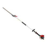
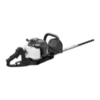
EH 25 Hedge trimmer (adjustable) (1)
EH 50 Hedge trimmer (adjustable) (1)
EP 100 Pole pruner (1)
EP 120 Pole pruner (1)
(1) Not approved for use with bike handle units
(DS 2700 T - DS 3000 T).