OWNER’S GUIDE GTS
®
800 541 4900 EFISPORTSMEDICINE.COM
13
GTS
®
OWNER’S GUIDE
OWNER’S GUIDE GTS
®
800 541 4900 EFISPORTSMEDICINE.COM
13
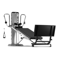
ADJUST THE RAIL ANGLE
To raise or lower the rail angle, stand alongside the Upper Rail (N), facing the Tower (A). Always have
one hand on the Tower (A) and one on the Upper Rail (N); lift the Rails (K, N) using proper lifting methods.
42. When you are raising the resistance level, lift the Rails (K, N) and slip the Tower Crossbar (Z)
into the desired Tower Hook (R). The higher the Rails (K,N) are on the Tower (A), the higher
the resistance. Once the Tower Crossbar (Z) connects with the desired Tower Hook (R),
lower the Rails (K, N) and make sure that the Tower Crossbar (Z) is securely seated inside
the Tower Hook (R).
HINT: At lower resistance levels, pulling the Tower (A) forward will help seat the Tower Crossbar
(Z), and you can push downward on the Rails (K, N) to insure the Tower Crossbar (Z) is seated.
IMPORTANT: Be sure the Tower Crossbar (Z) is fully secured in the Tower Hooks (R) on both
sides before use. Always perform a visual and manual check before getting on the GTS.
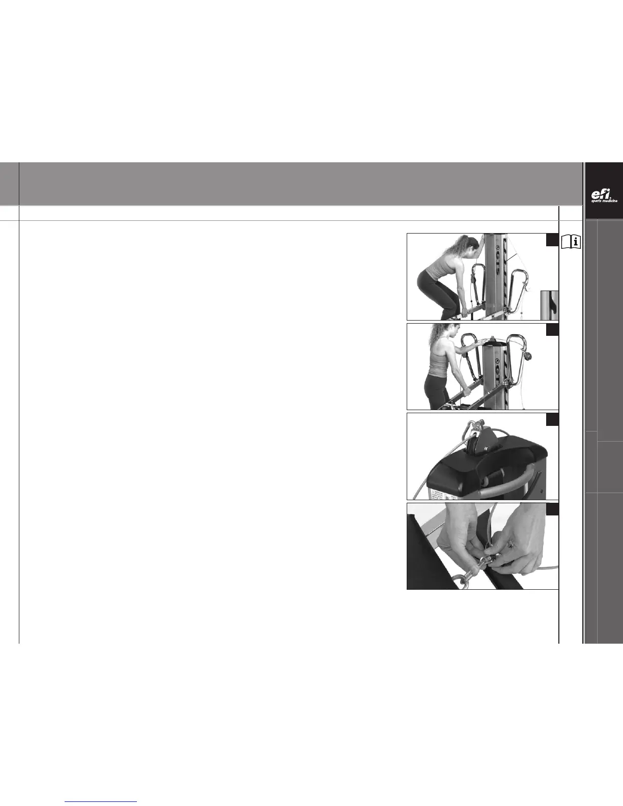
43. When lowering the resistance level, lift the Rails (K, N) to disengage the Tower Crossbar (Z)
from the Tower Hook (R). Push the Tower (A) back, and lower the Rails (K, N) to the desired
level. Once the Tower Crossbar (Z) aligns with the Tower Hook (R), pull the Tower (A) forward
and lower the Rails (K, N) until the Tower Crossbar (Z) is securely seated in the Tower Hook (R).
Push down on the Rails (K, N) to insure the Tower Crossbar (Z) is seated.
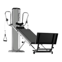
ATTACH AND DETACH DYNAMIC ARM PULLEY CABLE SYSTEM (W)
44. To attach the Dynamic Arm Pulley System (W) to the Glideboard (G), remove the center pulley
from the Tower Pulley Pocket (C) and connect the snap hook to the Glideboard “D” Ring (F).
45. To free the Glideboard (G) from the Dynamic Arm Pulley System (W), simply unfasten and
release the snap hook on the pulley, and store the center cable pulley in the Tower Pulley
Pocket (C).
42
43
44
45
Tower Hook
NOTE: Letters in (parentheses) refer to the PARTS IDENTIFIER on page 3 and/or the PARTS ASSEMBLY on page 4. Use as needed for clarification.