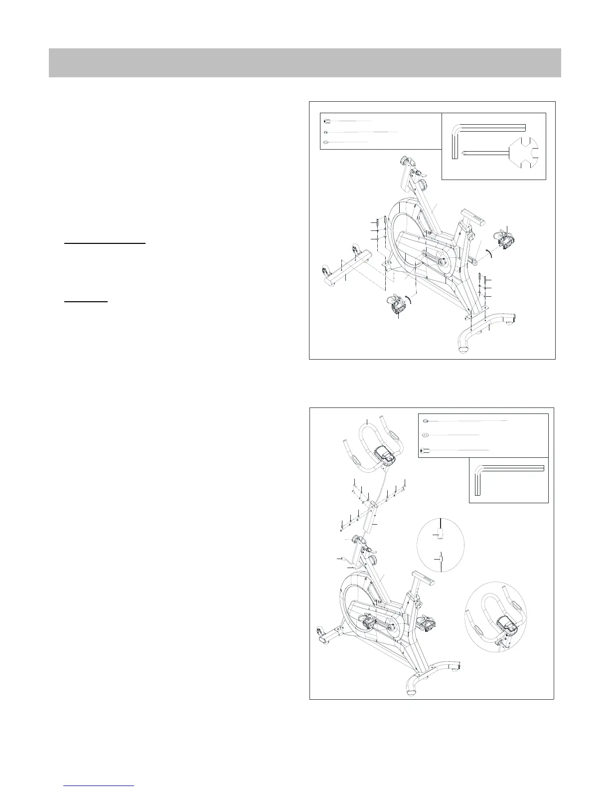
STEP 1:
Attach the Front & Rear Stabilizer (No.1 & 12)
to the Main Frame (No.81) using 4 Screws
(No.9), 4 Spring Washers (No.10) and 4
Washer (No.11). Tighten with an Allen
Wrench (No.94).
Attach Left Pedal (No.40L) to Left Crank
(No.39L). Turn the Left Pedal (No.40L)
counter-clockwise with the hand until it is
tight, then use Spanner (No.95) to securely
tighten. Attach Right Pedal (No.40R) to Right
Crank (No.39R). Turn the Right Pedal (No.40R)
clockwise with the hand until it is tight, then
use Spanner (No.95) to securely tighten.
Note: The Pedals (No.40L/R) are marked "L"
and "R" for Left and Right. Make sure you
attach the correct pedal to the corresponding
crank.
STEP 2:
Insert Trunk line (No. 88) through Handlebar
Post (No.74). Then attach the Handlebar
(No.78) to Handlebar Post (No.74) using 6
Screws (No.76), 6 Spring Washers (No.10),
and 6 washers (No.11). Tighten with an Allen
Wrench (No.94). (Figure B)
Loosen and pull out the Knob (No.13) from the
Main Frame (No.81). Insert the Handlebar
post (No.74) with Trunk line (No.88) into Main
frame (No.81) at desired position. Put back
and secure with the Knob (No.13).
Connect Trunk line (No.88) with Sensor Wire
(No.89). (Figure A)