EasyManua.ls Logo

Egcon AVR-126 - User Manual

Egcon AVR-126
7 pages
Print Icon
To Next Page IconTo Next Page
Loading...
1
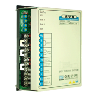
AUTOMATIC VOLTAGE REGULATOR
(MODEL : AVR-126)
WARNING :
To prevent personal injury or equipment damage, only qualified technicians /operators
should install, operate or service this device.
CAUTION :
Megger and high potential test equipment should not be used.
Incorrect use of such equipment could damage components contained in the regulator.
1. APPLICATION
:
AVR 125 is voltage regulator
to control brushless generator output by regulating
the current into the generator exciter field.
2. FEATURES :
2.1. Available for low resistance exciter filed.
2.2. Under frequency protection circuit.
When the generator frequency drops below the set point, generator output voltage is decreased with
the curve proportional to the frequency.
2.3. Over excitation
When the generator excitation field voltage exceeds 85Vdc, AVR output shut down to protect the
generator winding coil from burning out.
2.4. Starting engine generator set, if the residual voltage remains on the stator winding of generator,
AC output voltage is built up rapidly.
2.5. Durable under dust, damp and vibration.
2.6. Response time, below 25ms(1.5cycles)
3. SPECIFICATIONS
3.1. Input : 190~277Vac, 1
Φ
, 50/60Hz, Burden 650VA (terminal 3-4)
3.2. Output :
MODEL VOLTAGE CURRENT REMARKS
AVR - 125 125Vdc 15A continuous
Maximum current (for 1min.) - 20A
3.3. Sensing : 1
Φ
,190 ~ 240Vac (220V sensing – terminal 4-3)
1
Φ
,380 ~ 400Vac (380V sensing – terminal 4-E1)
3.4. Exciter field resistance : 2ohms to 100ohms
3.5. External voltage adjust rheostat : 1
, 2W (out of supply scope)
3.6. Voltage adjust range
Coarse adjusting (by internal rheostat)
±
12.5%
Fine adjusting (by external rheostat)
±
5%
3.7. voltage regulating accuracy
±
1.0%
3.8. Voltage build up condition internally and automatically raised by the residual voltage from the
Generator stator winding (minimum 3Vac)

Questions and Answers

Summary

Application

AVR Functionality

Controls brushless generator output by regulating exciter field current.

Product Features

Low Resistance Exciter Field Support

Available for low resistance exciter field applications.

Under Frequency Protection

Decreases output voltage proportionally as generator frequency drops below set point.

Over Excitation Shutdown

Shuts down AVR output if excitation field voltage exceeds 85Vdc.

Rapid Voltage Buildup

AC output voltage builds up rapidly when residual voltage is present on stator winding.

Durability

Durable under dust, damp, and vibration conditions.

Fast Response Time

Response time below 25ms (1.5 cycles).

Technical Specifications

Input Power Requirements

190-277Vac, 1 Phase, 50/60Hz, 650VA burden.

Output Power Ratings

125Vdc output, 15A continuous current, 20A max for 1 min.

Voltage Sensing Options

Supports 190-240Vac (220V sensing) and 380-400Vac (380V sensing).

Exciter Field Resistance Range

Compatible with exciter field resistance from 2 to 100 ohms.

External Voltage Adjustment

Requires 1kΩ, 2W rheostat (not supplied) for external voltage adjustment.

Voltage Adjustment Range

±12.5% coarse adjustment (internal), ±5% fine adjustment (external).

Voltage Regulating Accuracy

±1.0% voltage regulating accuracy.

Voltage Build-up Condition

Automatically builds up voltage from residual voltage (min 3Vac).

Over Excitation Shutdown Threshold

Shuts down if exciter voltage exceeds 85±5Vdc for 10sec or 100Vdc instantaneously.

Operating and Storage Temperatures

Operates -20°C to 50°C; Stores -40°C to 85°C.

Structure

Dimensions and Mounting

Size W140xH200xD60mm; Mounting W90xH190mm.

Physical Characteristics

Ivory color, approx. 2kg weight.

Frequency Selection

Features a changeover switch for frequency selection.

Instruction and Connection

Pre-Mounting Check

Verify regulator output current meets exciter capacitor requirements.

Mounting Recommendations

Mount in generator conduct box or switch gear, front panel vertical.

Connection Guidelines

Refer to provided drawings for correct wiring connections.

Adjusting

Initial Startup and Voltage Buildup

Start engine, bring to speed; voltage should build up automatically.

Troubleshooting Voltage Buildup

Check DC connection or perform field flashing if voltage fails to build up.

Voltage Potentiometer Adjustment

Adjust volt potentiometer until nominal voltage is reached.

Stability Adjustment

Adjust stab potentiometer if voltage is unstable.

Frequency Switch Operation

Select frequency switch (SW1) based on generator frequency for protection.

Flash Exciting Procedures

Manual Field Flash Exciting

Procedure for manual field flash exciting when generator fails to build up.

Automatic Field Flash Exciting

Recommended automatic field flash exciting using generator control sequence.

Parallel Operation

Droop Performance for Inductive Load

Connect external resistance for droop performance with inductive loads.

Troubleshooting

Residual Voltage - No Output

Check connections, flash field, or replace fuse/regulator/generator.

Output Voltage Low

Check connections, adjust voltage up, or replace regulator.

Output Voltage High

Adjust voltage down or replace regulator.

Output Voltage High - No Adjustment

Replace defective regulator.

Rating Output Voltage Behavior

Check generator exciter/diode or reverse adjust wiring.

Generator Output Voltage Hunting

Rotate stability adjust CW until hunting stops.

Poor Regulation

Replace defective regulator.

Overview

The Automatic Voltage Regulator (AVR-126) is a device designed to control the output of brushless generators by regulating the current supplied to the generator's exciter field. It is crucial to note that only qualified technicians and operators should install, operate, or service this device to prevent personal injury or equipment damage. The use of megger and high potential test equipment is cautioned against, as it can damage the internal components of the regulator.

Function Description:

The primary function of the AVR-126 is to maintain a stable output voltage from a brushless generator. It achieves this by precisely controlling the excitation current, which in turn influences the magnetic field and thus the generated voltage. The device is particularly suited for generators with low resistance exciter fields.

Important Technical Specifications:

  • Input: The AVR-126 accepts a single-phase input of 190 to 277 Vac at 50/60 Hz. The burden for this input is 650 VA (connected to terminals 3-4).
  • Output: The regulator provides a continuous output of 125 Vdc at 15 A. It can handle a maximum current of 20 A for up to 1 minute.
  • Sensing: The device offers flexible sensing options:
    • Single-phase 190 to 240 Vac for 220V sensing (terminal 4-3).
    • Single-phase 380 to 400 Vac for 380V sensing (terminal 4-E1).
  • Exciter Field Resistance: Compatible with exciter field resistances ranging from 2 ohms to 100 ohms.
  • External Voltage Adjust Rheostat: Requires an external 1 kΩ, 2W rheostat for fine voltage adjustment (not included in the supply scope).
  • Voltage Adjust Range:
    • Coarse adjustment (internal rheostat): ±12.5%
    • Fine adjustment (external rheostat): ±5%
  • Voltage Regulating Accuracy: Achieves a high accuracy of ±1.0%.
  • Voltage Build-up Condition: The AVR-126 is designed for rapid voltage build-up. It internally and automatically raises the output voltage using the residual voltage from the generator stator winding, requiring a minimum of 3 Vac.
  • Over Excitation Shut Down: A critical safety feature, the AVR-126 will remove its output if the exciter field voltage exceeds 100 Vdc instantaneously. Alternatively, if the exciter field voltage remains above 85 ±5 Vdc for 10 seconds, the output will also be shut down. To reset the regulator after a shutdown, the generator set must be stopped, or the power input to the AVR must be interrupted for more than 20 seconds.
  • Operating Temperature: Designed to operate in a wide temperature range from -20°C (-8°F) to 50°C (140°F).
  • Storage Temperature: Can be stored in temperatures ranging from -40°C (-40°F) to 85°C (185°F).
  • Response Time: Boasts a fast response time of less than 25 milliseconds (1.5 cycles).
  • Dimensions: W140 x H200 x D60 mm.
  • Mounting Size: W90 x H190 mm with 5Φ - 4Holes.
  • Weight: Approximately 2 kg.

Usage Features:

  • Under Frequency Protection Circuit: This feature protects both the generator and the AVR. If the generator frequency drops below a predefined set point, the generator output voltage is proportionally decreased along a specific curve, preventing damage. The frequency selection can be set for either 50Hz or 60Hz systems via a changeover switch.
  • Durable Construction: The AVR-126 is built to be durable and resistant to dust, dampness, and vibration, making it suitable for various operating environments.
  • Rapid Voltage Build-up: When starting the engine generator set, if residual voltage is present on the stator winding, the AC output voltage builds up quickly.
  • Remote Voltage Adjust: The device allows for remote voltage adjustment by removing a jumper between terminals 6 and 7 and connecting an external potentiometer (rheostat) to these terminals.
  • Adjustable Stability: A "stab" potentiometer allows for adjustment of the regulator's stability. Turning it clockwise increases the damping level for generator transient output voltage, while turning it counter-clockwise decreases damping, which could lead to under-damping. Adjusting stability also changes the response time of the regulator.
  • Mounting Recommendations: For optimal performance and ease of access, it is recommended to mount the AVR in the generator conduit box or the generator control and switch gear, ensuring the front panel is visible and all marks are straight in the vertical plane. Prior to mounting, the generator manufacturer should verify that the regulator's output current meets the exciter's requirements.
  • Manual Field Flash Exciting: If the generator fails to build up to its rated voltage or has no output, a manual field flash exciting procedure can be performed using a 12Vdc battery and a push button. This involves temporarily connecting the battery to the exciter field to initiate voltage build-up.
  • Automatic Field Flash Exciting: To prevent no output voltage upon starting the generator set, an automatic field flash exciting sequence can be implemented as part of the generator control system.
  • Parallel Operation (with modification): While AVR 125 is not designed for parallel operation by default, it can be adapted for droop performance with inductive loads. This requires connecting an external variable resistance with a toggle switch in series with one of the two input sensing lines to the regulator.

Maintenance Features:

  • Troubleshooting Guide: The manual provides a comprehensive troubleshooting guide with common symptoms, their potential causes, and recommended actions. This includes issues such as:
    • Residual Voltage - No Output: Causes include low residual voltage, disconnected field leads, disconnected power input leads, blown fuse, or a defective regulator/generator. Actions range from checking wiring and flashing the field to replacing components or consulting the generator manual.
    • Output Voltage Low/High: Often caused by incorrect voltage adjustments (internal or remote rheostat) or a defective regulator. Solutions involve adjusting the potentiometers or replacing the regulator.
    • Output Voltage High - No Adjustment: Indicates a defective regulator.
    • Rating Output Voltage at no load and Voltage Down at load condition: Points to a defective generator, requiring a check of the exciter and rotating diode.
    • Remote Voltage Adjust Operates Backwards: Suggests incorrect wiring of the remote voltage adjust.
    • Generator Output Voltage Hunting: Typically caused by a defective regulator, requiring rotation of the stability adjust.
    • Poor Regulation: Indicates a defective regulator.

Egcon AVR-126 Specifications

General IconGeneral
BrandEgcon
ModelAVR-126
CategoryController
LanguageEnglish