56 VOLT LITHIUM-ION CORDLESS LINE TRIMMER — ST1300E 9
Cutting Width 33 cm
Recommended Operating Temperature
0°C-40°C
Recommended Storage Temperature
-20°C-70°C
Weight (without battery pack) 2.76 kg
Measured sound power level L
WA
89.25 dB(A)
K=2.5 dB(A)
Max. sound pressure level at
operator’s ear L
PA
75.2 dB(A)
K=2.5 dB(A)
Guaranteed sound power level L
WA
(according to 2000/14/EC)
93 dB(A)
Valuation of
vibration a
h
Front handle
2.134 m/s
2
K=1.5 m/s
2
Rear handle
1.231 m/s
2
K=1.5 m/s
2
◾ The declared vibration total value has been measured
in accordance with a standard test method and may be
used for comparing one tool with another;
◾ The declared vibration total value may also be used in
a preliminary assessment of exposure.
NOTICE: The vibration emission during actual use of the
power tool can differ from the declared value in which the
tool is used;In order to protect the operator, user should wear
gloves and ear protectors in the actual conditions of use.
PACKING LIST
PART NAME QUANTITY
Line Trimmer 1
Guard 1
Front-assist Handle Assembly 1
Hex Wrench 1
Operator’s Manual 1
DESCRIPTION
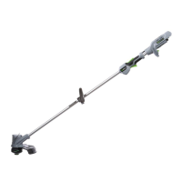
KNOW YOUR LINE TRIMMER (Fig. A)
1. Trigger
2. Rear Handle
3. Lock-off Lever
4. Speed Adjustment Switch
5. Soft Sleeve
6. Adjustable Front-assist Handle
7. Trimmer Head (Bump Head)
8. Bump Knob
9. Line-cutting Blade
10. Guard
11. Ejection Mechanism
12. Electric Contacts
13. Latch
14. Battery-release Button
ASSEMBLY
WARNING: If any parts are damaged or missing,
do not operate this product until the parts are replaced.
Use of this product with damaged or missing parts could
result in serious personal injury.
WARNING: Do not attempt to modify this product or
create accessories not recommended for use with this line
trimmer. Any such alteration or modification is misuse and
could result in a hazardous condition leading to possible
serious personal injury.
WARNING: To prevent accidental starting that could
cause serious personal injury, always remove the battery
pack from the tool when assembling parts.
MOUNTING THE GUARD
WARNING: Always wear gloves when mounting or
replacing the guard. Take care of the blade on the guard
and protect your hand from cutting.
WARNING: Never operate the tool without the
guard firmly in place. The guard must always be on the
tool to protect the user! When the guard was fixed,
never attempted to remove or adjust the guard, if
replace needed, it shall be performed by a qualified
service technician!
Loosen and remove the two combination screws from the
shaft base (Fig. B). Align the guard mounting holes with
the assembly holes and then lock the guard onto the shaft
base with the two screws. Make sure the guard is fixed
according to Fig. B & C, any reverse fixing will cause
great danger!
MOUNTING AND ADJUSTING THE FRONT-ASSIST
HANDLE
Push the front-assist handle onto the shaft (Fig. E), then
insert the clamping block into the handle slot (Fig. F),
mount the lock pole, lock them with the wing nut (Fig.
G). The sequence is as Fig. D shown. Lastly, adjust the
front-assist handle position to make sure your front arm
is straight when using the trimmer (Fig. H) and then lock
the lever of the lock pole (Fig. I).
Fig. D & H parts description see below:
D-1 Front-assist Handle D-4 Wing Nut
D-2 Lock Pole H-1 Soft Sleeve