HC960 Operating Instructions
8/14 Version 2.1 © ehb Errors
excepted
Bedienungsanleitung.doc • Stand/Version: 25.02.2005/00 • Layout: Gottschalk • \\Ehelec-nts-000\EHELEC\Iso 9001\Formblätter\Vorlagen
7. Operating hours counter
The HC960 has two independent operating hours counters: A resettable daily operating hours counter,
which can be used for maintenance intervals, for example, and a settable total operating hours counter.
While the blade shaft rotates, its speed is automatically displayed. If you wish to display the daily operat-
ing hours instead, briefly press the set button once in fully automatic mode (Normal RPM greater than
zero). In semi-automatic mode (Normal RPM equals zero), however, the set button must be pressed for
longer than 3 seconds, as in this operating mode a brief keystroke will cause a new target speed to be
adopted.
To clear the daily operating hours counter, press the set button for longer than 3 seconds in both operat-
ing modes. After these 3 seconds have elapsed, there is a switchover to the display of the daily operating
hours. After a further 3 seconds (the set button is still pressed), the daily operating hours counter is
cleared. “0:00" appears. The specified times apply in each case starting from the speed display.
If no button is pressed for ten seconds, there is an automatic switchover back to the speed display.
When the blade shaft is stationary, the total operating hours (th = total hours) automatically appear in the
display. Here too, briefly pressing the set button switches to the display of daily operating hours.
The procedure described above for resetting the daily operating hours counter also applies here. If no
button is pressed for ten seconds, the display automatically switches to the total operating hours.
The total operating hours counter can be set via the parameter menu.
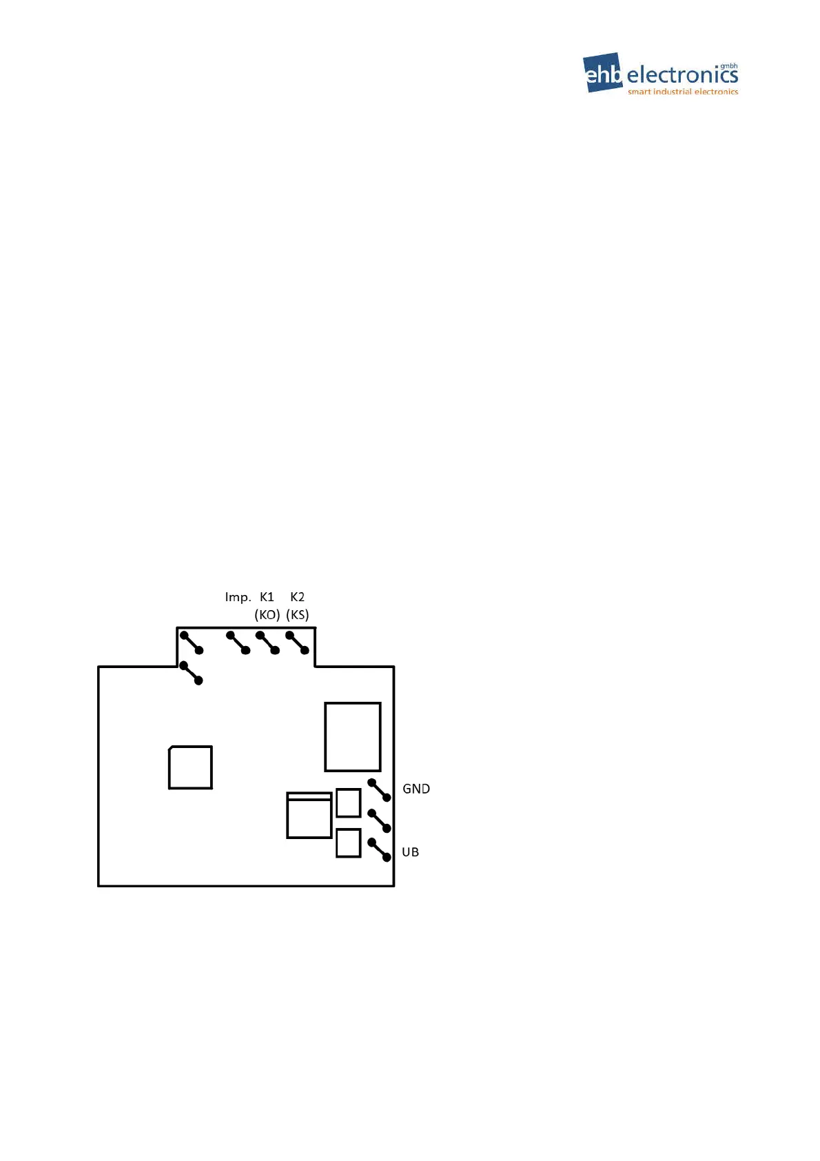
8. Output assignment
Depending on whether you need a N.O. or a N.C. contact for your magnet of the feed control, select the
appropriate contact on the HC960. Please also note the function of the output states, which are described
in detail in Figure 1 on page 4.
Pin assignment