Do you have a question about the Ei Electronics Ei128R and is the answer not in the manual?
Explains the relay function, power, and continuous/pulse operation modes for alarms.
Highlights critical safety precautions for installation, power sources, and wiring of relay bases.
Emphasizes disconnecting mains power and securely attaching the apparatus before installation.
Details the process of installing the relay base directly underneath an Ei Alarm base.
Explains how to install the relay base in a separate location convenient for wiring.
Provides instructions on connecting the relay contacts to an auxiliary device for control.
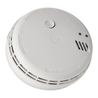
The Ei128R and Ei128RBU Relay Bases are designed to integrate with mains-powered Ei Alarms, providing a crucial link for enhanced safety and system control. Their primary function is to switch an internal relay upon receiving an alarm signal from an interconnected Ei Alarm. This capability allows for a wide array of applications, significantly extending the utility of a standard alarm system. For instance, these relay bases can be configured to automatically shut off the mains supply to boilers in the event of an alarm, preventing potential escalation of hazards. They can also trigger alarm panels, activate auxiliary warning devices, or interface with building management systems, offering a versatile solution for various safety and control needs.
Both models are powered by a 230VAC mains supply, ensuring continuous operation within a typical household or commercial electrical setup. A key distinction between the two models is the Ei128RBU, which incorporates rechargeable back-up cells. This feature is particularly valuable as it allows the relay to continue functioning even during a mains power failure, provided the interconnected mains-powered alarm also has battery back-up. The rechargeable cells in the Ei128RBU can power the relay for up to two months when the mains are off, offering a robust solution for maintaining safety functions during extended power outages. In contrast, the Ei128R model does not have battery back-up and will not switch during mains failure.
The installation of the Relay Bases is flexible. They can be conveniently installed directly underneath an Easi-fit Alarm base, creating a compact and integrated unit. Alternatively, they can be sited separately, offering greater flexibility in placement, especially when needing to be closer to the auxiliary device they control. This adaptability ensures that the Relay Bases can be integrated into diverse environments and existing alarm setups without significant modifications.
A notable usage feature of these Relay Bases is their configurable relay operation mode. As supplied, the relay operates continuously, meaning it switches when an alarm sounds and remains switched until an alarm cancel signal is received. This continuous mode is suitable for applications requiring a sustained response, such as keeping a boiler off or an alarm panel triggered until the situation is resolved. However, for applications requiring only a momentary signal, the user can move a slide switch to the 'P' (pulse) position. In this mode, the relay will switch when an alarm sounds but will automatically switch back after five seconds. This pulse mode is commonly used with warden call systems or other scenarios where a brief short-circuit signal is sufficient to trigger a response.
The Relay Bases are designed to be used in both 230VAC and low voltage applications. The Ei128RBU model, with its rechargeable back-up cells, is particularly well-suited for low voltage applications where maintaining functionality during power interruptions is critical. This versatility makes the Relay Bases adaptable to a wide range of auxiliary devices and control systems.
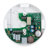
For installation under an Easi-fit Alarm, the process involves selecting a mounting position based on the alarm manual, preparing the wiring by removing appropriate knockouts for surface-mounted conduit, and connecting the power supply wires (Live & Neutral) to the relay base's mains terminal block. If an earth wire is present, it should be connected directly to the alarm mounting plate. The three wires (Live, Neutral, and Interconnect) from the Relay Base are then connected to the corresponding terminals on the Alarm's mounting plate. The 'IC' (Interconnect) wire must be connected even in a single alarm installation to ensure proper communication. If the central knockout is used, it's crucial to seal around the wires with silicone to prevent air draughts that could affect the alarm's performance.
When installing the Relay Base away from the alarm, the supplied cover must be fitted to protect the user from fire or shock hazards. The alarm(s) are installed as per their manuals, and the Relay Base is then installed near the auxiliary device or in a convenient location for wiring. The wiring from one of the alarms is brought through a knockout to the Relay Base's mains terminal block, connecting the Live, Neutral, and Interconnect wires.
Wiring the relay section involves connecting the L (Live) wire from the auxiliary device's power supply to the C (Common) terminal of the Relay Base. Depending on the required control action for the auxiliary device, either the NC (Normally Closed) or NO (Normally Open) contact of the relay is then connected to the auxiliary device. For example, to cut out a boiler during an alarm, the NC contact would be used. For a beacon that should only activate during an alarm, the NO contact would be appropriate. If the auxiliary device is powered from the same 230VAC circuit as the alarms and Relay Base, a link wire can be inserted between the L (Live) terminal and the C (Common) terminal of the Relay Base, simplifying the wiring.
Maintenance features include recommended monthly checks of the alarm system, which should also involve checking the Relay Base. Users should verify that the green LED power indicator on the alarm is lit, indicating proper electrical connection. If it's off, the circuit breaker, fuse, or wiring should be checked. Pressing the alarm test button should confirm that the relay switches and the auxiliary device behaves as expected.
For the Ei128RBU model, it's important to annually check the rechargeable cells. This involves disconnecting the mains supply, checking the relay operation as described above, and then reconnecting the mains if satisfactory. If the relay fails to operate, the unit is defective and requires replacement. The operational life of the Relay Base is 10 years, after which it must be replaced.
It is crucial to note that a maximum of 12 alarms can be interconnected to one Relay Base. When one alarm sounds, all interconnected alarms will sound, and the relay will switch. A significant safety consideration is the interconnection of Carbon Monoxide Alarms with Smoke/Heat Alarms. This should only be done if an Ei1529RC control switch is used in the system. This control switch allows users to quickly identify the source of the alarm (fire or CO gas), enabling appropriate action—opening windows for CO incidents versus slowing down a fire.
The Relay Bases are designed for connection to a Pure or True Sine Wave 230V AC supply. If connecting to alternative energy sources like PV solar panels or UPS systems that utilize an inverter, the Total Harmonic Distortion (THD) must be less than 5%. The Relay Bases must not be powered from a light dimmer circuit.
The product is not waterproof and must not be exposed to dripping or splashing. Installation and interconnection must be performed by a qualified electrician in accordance with relevant local regulations to prevent shock or fire hazards. An all-pole mains switch must be incorporated into the electrical installation of the building. Interference with the Relay Base or attempts to tamper with it will invalidate the guarantee and may expose the user to shock or fire hazards. Auxiliary devices connected to the relay contacts will only give a warning after the contacts have switched for at least 200mSec.
| Power Source | Battery |
|---|---|
| Test Button | Yes |
| LED Indicator | Yes |
| Hush Feature | Yes |
| Standards | EN 14604:2005 |
| Type | Smoke Alarm |
| Battery Type | 9V Alkaline |
| Sensor Type | Optical |
| Alarm Volume | 85dB |
| Interconnectability | Yes |