installer so that any copper Earth wire or cable coloured
green & yellow, can be safely terminated.
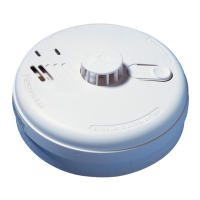
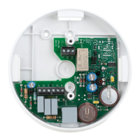
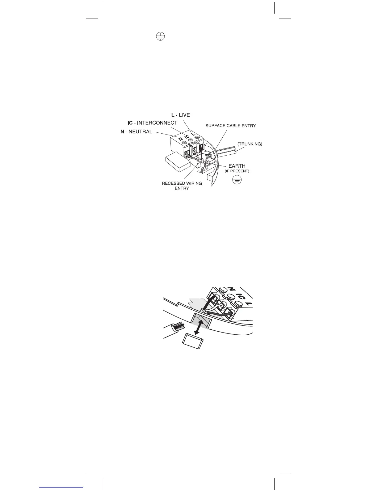
To interconnect the Alarms connect all the IC terminals
together as shown in Figure 4 (see “Interconnecting
Alarms” section on page 14).
4. If the mains wires are recessed, bring the wires
through the rear hole in the mounting plate as shown
in Figure 4.
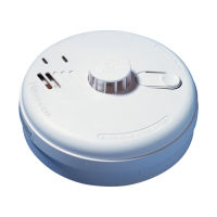
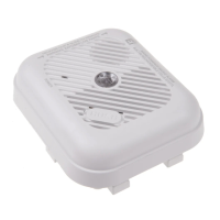
If the mains wires are being brought along the surface:
(a) position the mounting plate so the cable trunking is
as shown in Figure 4.
(b) the mounting plate has a removable section, take it
out to interface directly with 25 mm conduit as shown in
Figure 5. If interfacing to 16 mm conduit carefully cut
around the marked section, leaving the top intact and
replace the section. (If you are not using surface wiring,
the removable section must be left in place for electrical
safety reasons).
There are two other positions which are also suitable for
the surface wiring to enter (and exit) the alarm, one next
to the removable section and another directly opposite.
5. Carefully align the mounting plate and screw into
place. Connect the wires to the terminal block. With
recessed wiring, ensure the rear gasket seals around
the edge of the hole in the ceiling or wall. This is to
prevent air draughts affecting the smoke/heat entering
the alarm. If the hole is too large or the alarm does
not seal it, it should be sealed with silicone rubber or
equivalent.
6. Replace the wiring cover. Check the alarm battery is
connected (Ei141/144/146 only).
13
REMOVEABLE
TRUNKING DOOR FOR
Figure 4
Figure 5