GB
- 20 -
L
pA
sound pressure level ..................... 83.1 dB(A)
K
pA
uncertainty .............................................3 dB
L
WA
sound power level ....................... 94.1 dB(A)
K
WA
uncertainty .............................................3 dB
Wear ear-muff s.
The impact of noise can cause damage to hea-
ring.
Total vibration values (vector sum of three direc-
tions) determined in accordance with EN 60745.
Handle
Vibration emission value a
hAG
= 8.050 m/s
2
K uncertainty = 1.5 m/s
2
Additional handle
Vibration emission value a
hAG
= 5.402 m/s
2
K uncertainty = 1.5 m/s
2
The specifi ed vibration value was established in
accordance with a standardized testing method. It
may change according to how the electric equip-
ment is used and may exceed the specifi ed value
in exceptional circumstances.
The specifi ed vibration value can be used to
compare the equipment with other electric power
tools.
The specifi ed vibration value can be used for initi-
al assessment of a harmful eff ect.
Keep the noise emissions and vibrations to a
minimum.
•
Only use appliances which are in perfect wor-
king order.
•
Service and clean the appliance regularly.
•
Adapt your working style to suit the appliance.
•
Do not overload the appliance.
•
Have the appliance serviced whenever ne-
cessary.
•
Switch the appliance off when it is not in use.
•
Wear protective gloves.
Caution!
Residual risks
Even if you use this electric power tool in
accordance with instructions, certain resi-
dual risks cannot be rules out. The following
hazards may arise in connection with the
equipment’s construction and layout:
1. Lung damage if no suitable protective dust
mask is used.
2. Damage to hearing if no suitable ear protec-
tion is used.
3. Health damage caused by hand-arm vib-
rations if the equipment is used over a pro-
longed period or is not properly guided and
maintained.
5. Before starting the equipment
Warning!
Always remove the battery pack before making
adjustments to the equipment.
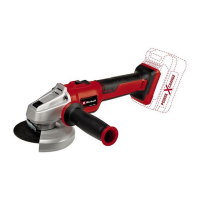
5.1 Fitting the additional handle (Fig. 2)
•
The angle grinder must not be used without
the additional handle (3).
•
The additional handle can be secured in any
of two positions (A, B).
Tool side Suitable for
Left (position A / as
shown)
Right-handed users
Right (position B) Left-handed users
5.2 Replacing and adjusting the guard (Fig. 3)
Replacing:
•
Remove the quick-clamp nut (5) and the
clamping flange underneath.
•
Open the clamp lever (f) on the guard (4).
•
Turn the guard (4) through 180° in clockwise
direction so that the guard points upwards.
•
Remove the guard (4).
To mount, proceed in the reverse order.
Adjusting:
•
Adjust the guard (4) to protect your hands
so that the material being ground is directed
away from your body.
•
The position of the guard (4) can be adjusted
to any specific working conditions. Undo the
clamp handle (f) and turn the cover (4) into
the required position.
•
Ensure that the guard (4) correctly covers the
gear wheel casing.
•
Secure the clamp handle (f) again.
•
Ensure that the guard (4) is secure.
Anl_Axxio_18_115_Q_SPK9.indb 20Anl_Axxio_18_115_Q_SPK9.indb 20 20.04.2020 06:58:1520.04.2020 06:58:15
 Loading...