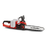
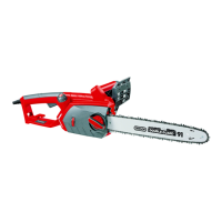
4. Technical data
Engine displacement 37.2 cm
3
Maximum engine capacity 1.2 kW
Bar length 32 cm
Cutter rail length 14” (35 cm)
Chain pitch (3/8”), 10 mm
Chain thickness (0.05”), 1.27 mm
Idling speed 3200 rpm
Maximum speed with cutting equipment 11000 rpm
Tank capacity 310 ml
Oil tank capacity 210 ml
Anti-vibration function Yes
Chain wheel teeth 6 x 9.525 mm
Chain brake Yes
Clutch Yes
Automatic chain lubrication Yes
Low-kickback chain Yes
Net weight without chain and chain bar 4.55 kg
Net weight (dry) 5 kg
Fuel consumption (specific) 560 g / kWh
L
pA
sound pressure level 100 dB(A)
L
WA
sound power level 112 dB(A)
Vibration a
hv
(front handle) max. 5.46 m/s
2
Vibration a
hv
(rear handle) max. 6.21 m/s
2
Chain type OREGON (91PO53X)/
CARLTON (N1C-BL-52E SK B)
Bar type
OREGON (140SDEA041)/QIRUI (PO14-50SR)
Spark plug L8RTF
5. Before starting the equipment
Important: Do not start the engine until the saw
is fully assembled.
Important: Wear protective gloves at all times
when handling the chain.
5.1 Fit the chain bar
To ensure that the bar and the chain are supplied
with oil, USE ONLY THE ORIGINAL BAR. The oiling
hole (Fig. 2/Item A) must be kept clear of dirt and any
build-up of residue.
1. Make sure the Chain brake lever is pulled back
into the DISENGAGED position (Fig. 3A)
2. Remove the two bar fastening nuts (B). Remove
the cover (Fig. 3B).
Important: When assembling for the first time,
the material fitted to provide protection during
transportation (Fig. 3C/Item 24) must be removed
first.
3. Using a screwdriver, run the adjustment screw
(D) COUNTERCLOCKWISE until the TANG (E)
(projecting prong) is to the end of its travel toward
the clutch drum and sprocket (Fig. 3B/3C).
4. Fit the open end of the chain bar over the die bar
pins (F) (Fig. 3C/3D).
5.2 To install saw chain
1. Spread chain out in a loop with cutting edges (A)
pointing CLOCKWISE around loop (Fig. 4A).
2. Slip the chain around the sprocket (B) behind the
clutch (C). Make sure the links fit between the
sprocket teeth (Fig. 4B).
3. Guide the drive links into the groove (D) and
around the end of the bar (Fig. 4B).
NOTE: The saw chain may droop slightly on the lower
part of bar. This is normal.
4. Pull the chain bar forward until the chain is closely
seated. Make sure that all the drive links are in
the groove of the bar.
5. Fit the clutch cover and fasten it with 2 screws.
Make sure that the pivot (Fig. 3C/Item E) fits into
the chain bar (Fig. 3D/Item G). The chain must
not slip off the bar when you do this. Tighten the
two nuts by hand and then follow the instructions
for adjusting the tension in ADJUSTING THE
CHAIN TENSION.
5.3 Saw chain tension adjustment
Proper tension of saw chain is extremely important
and must be checked before starting, as well as
during any cutting operation.
Taking the time to make needed adjustments to the
saw chain will result in improved cutting performance
and prolonged chain life.
Warning: Always wear heavy duty gloves when
handling saw chain or making saw chain adjustments.
1. Hold nose of guide bar up and turn adjustment
screw (D) CLOCKWISE to increase chain
tension. Turning screw COUNTERCLOCKWISE
will decrease amount of tension on chain. Ensure
the chain fits snugly all the way around the guide
bar (Fig. 5).
2. After making adjustment, and while still holding
nose of bar in the uppermost position, tighten the
bar retaining nuts securely. Chain has proper
21
GB