14
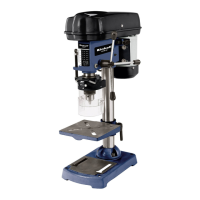
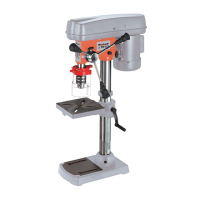
5. Technical data
Nominal input voltage 230V ~ 50 Hz
Power rating 630 W
Operating mode S2 15 min.
Motor speed 1,400 rpm
Output speed 240 – 2,520 rpm
Speed levels 12
Drill chuck mount B 16
Scroll chuck Ø 1.5 - 16 mm
Max. shaft diameter 16 mm
Reach 126 mm
Dimensions of drill table 200 x 195 mm
Angle adjustment of table 45° / 0° / 45°
Drill depth 60 mm
Pillar diameter 60 mm
Height approx. 850 mm
Base area 350 x 230 mm
Weight 33.5 kg
L
pA
sound pressure level 74 dB(A)
L
WA
sound power level 87 dB(A)
K
pA
uncertainty 3 dB
K
WA
uncertainty 3 dB
Sound and vibration
Sound and vibration values were measured in
accordance with EN 61029.
Load factor:
A load factor of S2 15 min (intermittent periodic duty)
means that you may operate the motor continuously
at its nominal power level (630 W) for no longer than
the time stipulated on the specifications label (15
minutes ON period). If you fail to observe this time
limit the motor will overheat. During the OFF period
the motor will cool again to its starting temperature.
Warning!
The specified vibration value was established in
accordance with a standardized testing method. It
may change according to how the electric equipment
is used and may exceed the specified value in
exceptional circumstances.
The specified vibration value can be used to compare
the equipment with other electric power tools.
The specified vibration value can be used for initial
assessment of a harmful effect.
Keep the noise emissions and vibrations to a
minimum.
Only use appliances which are in perfect working
order.
Service and clean the appliance regularly.
Adapt your working style to suit the appliance.
Do not overload the appliance.
Have the appliance serviced whenever
necessary.
Switch the appliance off when it is not in use.
Wear protective gloves.
Residual risks
Even if you use this electric power tool in
accordance with instructions, certain residual
risks cannot be rules out. The following hazards
may arise in connection with the equipment’s
construction and layout:
1. Lung damage if no suitable protective dust mask
is used.
2. Damage to hearing if no suitable ear protection is
used.
3. Health damage caused by hand-arm vibrations if
the equipment is used over a prolonged period or
is not properly guided and maintained.
6. Before starting the equipment
6.1. Installing the machine (Fig. 1/3/4)
Place the base plate (1) in the desired position.
Fasten the pillar (2) with flange using the supplied
screws (3).
Insert the screw gear in the drill table support.
Then insert the gear rack (30) in the drill table
support (5) with the teeth facing the screw gear
(identical projection).
Now slip these parts together over the pillar (2). In
doing so, make sure that the gear rack is correctly
seated in the teeth of the screw gear.
To secure the gear rack at the top end, slip on the
guide sleeve (29) over the pillar and fasten with
the screw.
You can now fit the table and clamp in place with
the clamping lever. Following this, fit the crank
(27) and fasten tightly with the screw (28).
Finally, fit the complete bit head to the pillar. Align
the head so that it is horizontal to the base plate
and fasten it in position with the screws (35).
Screw the 3 supplied handles (9) in the handle
mounts.
Before you mount the drill chuck with the MK
shank, check that both parts are clean. Insert the
taper mandrel in the taper of the drill chuck with a
powerful jolt. Then insert the taper in the spindle
(Fig. 12)
GB