7. Assembly
Caution! Always pull out the power plug before
carrying out any maintenance or conversion
work.
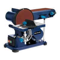
7.1 Assembling the machine (Fig. 1 - 6)
Fit the rubber feet (2) to the base (5).
Fasten the plastic guard (16) using the screws
(17) (Fig. 2).
Mount the sanding/grinding disk (13) on the
shaft (Fig. 3).
Tighten the screw (18) with the socket-wrench
(19) to fasten the sanding/grinding disk (13) (Fig.
3/4).
Mount the bottom disk guard (20) using the
screws (21) (Fig. 4).
Mount the sanding/grinding table (14) and fasten
using the screw (22) (Fig. 5).
The sanding/grinding table (14) can be infinitely
adjusted to any angle between 0° and 45° using
the mitre scale (23) and the knurled screw (2).
The adjustable cross stop (7) is for ensuring that
the workpiece is guided properly.
Caution! The sanding/grinding disk (13) must be
able to run freely. However, the gap between the
sanding/grinding table (14) and the
sanding/grinding disk (13) must not exceed
1.6 mm.
Mount the stop rail (12) and fasten with the
screws (24) and (25) (Fig. 6).
Caution! The sanding/grinding belt (11) must be
able to run freely.
7.2. Changing the sanding/grinding belt (11)
(Fig. 7 - 9)
Pull out the power plug.
Remove the screws (25) and (26).
Remove the sanding/grinding belt guard (27).
Turn the sanding/grinding belt clamp to the right
(9) to unclamp the sanding/grinding belt (11).
Remove the sanding/grinding belt (11) by lifting
out towards the back.
Mount the new sanding/grinding belt by
proceeding in reverse order.
Caution! Check the running direction: On the
casing (28) and on the inside of the
sanding/grinding belt!
7.3. Adjust the sanding/grinding belt (11) (Fig. 1)
Move the sanding/grinding belt (11) slowly by
hand in the direction of running.
The sanding/grinding belt (11) must run dead-
center on the sanding/grinding section (6). If it
does not do so, readjust it using the knurled
screw (10).
7.4. Adjusting the sanding/grinding position of
the sanding/grinding belt (11) (Fig. 10/11)
Slacken the two nuts (29).
Push the sanding/grinding belt (11) upwards to
the desired position.
Re-tighten the nuts (29) to fix the belt in this
position.
In this position the sanding/grinding table can be
used to support the workpiece. To do this, insert
the table in the hole in the stay tube (31) and
fasten using the screw (30).
7.5. Replacing the sanding/grinding paper on the
sanding/grinding disk (13)
Dismantle the bottom wheel guard (20) by
removing the 3 screws (21) (Figure 4). Pull the
sanding/grinding paper off the sanding/grinding
disk (13) and attach the new sanding/grinding
paper (quick-fit fastening system).
8. Using the machine
8.1. On/Off switch (1)
The machine can be switched on by pressing
the green pushbutton „1“.
The red pushbutton „0“ has to be pushed to
switch off the machine again.
8.2. Sanding/Grinding
Always hold the workpiece very firmly while
sanding/grinding.
Do not apply excessive pressure.
To prevent the sanding paper becoming worn on
just one side, move the workpiece backwards
and forwards during sanding/grinding on the
sanding/grinding belt or sanding/grinding plate!
Important! To prevent pieces coming off in
splinters, timber workpieces should always be
sanded along the direction of the grain.
9. Cleaning, maintenance and ordering
of spare parts
Always pull out the mains power plug before starting
any cleaning work.
9.1 Cleaning
Keep all safety devices, air vents and the motor
housing free of dirt and dust as far as possible.
Wipe the equipment with a clean cloth or blow it
with compressed air at low pressure.
We recommend that you clean the device
immediately each time you have finished using it.
13
GB