EIS
3.7. Manual Selection of
Installation Type
The first time that the microphone base is powered must be
defined the type of installation to which it is connected: 400
Series, New 100 Series or New 100 Series with call extension.
In any event, there is an option to allow for the manual selection
of this type of installation:
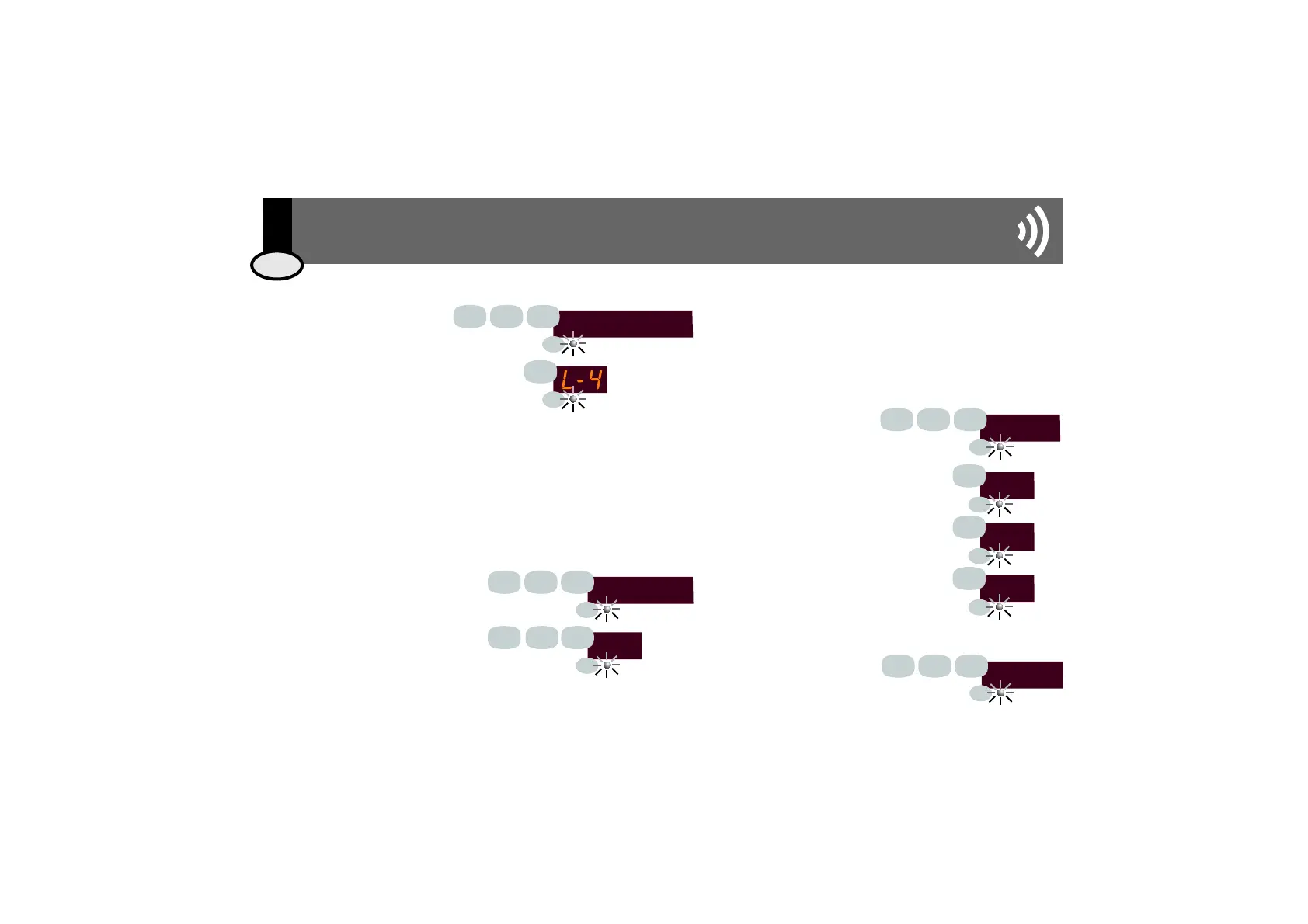
3.5. Adjusting Display Light Level
Key 912 followed by pressing the
PRG button.
Define the display light level by choosing
a value between 1 (minimum), 2
(medium), 3 (high) and 4 (maximum)
and press the PRG button to confirm.
Each and every Series 400 device installed is identified by a zone address that must
be unique to each one and have a value between 1 and 250 (see CC-1034 The
400 Series User and Installation Manual).
Each time the microphone base is connected to an installation, it initiates the
automatic process of assigning an address that is not being used at the time.
However, if the user wishes, the address can be changed by following these steps:
light level
9
2
1
4
3.6. Manual Assignment of Zone Address for
Intercom Microphone Base 13503
(Series 400 only)
3.8. Factory Reset
To reset programmed data
and return to the
microphone base's factory
configuration, key 951
followed by pressing the
PRG button.
RESET
9
5
1
19
EIS
Key 913 followed by pressing the PRG
button.
Define an address between the values
of 1 and 250 (for example, 192) and
press the PRG button.tecla PRG.
Key 914 followed by
pressing the PRG button.
Key 1 and then PRG for the New 100
Series, only general call (see E100/1
diagram)
Key 2 and then PRG for the New 100
Series with zone extension (see E100/2
and E100/3 diagrams)
Key 3 and then PRG for the 400 Series
(see E400 diagram)
The microphone base will then verify whether or not the address is available
and, if so, will take it as its own. If, however, the address has already been
assigned to another element in the installation (a control unit, a PC interface or
another base), it will restart the process.
PRG
PRG
PRG
PRG
ADDRESS
192
9
9
2
1
1
3
PRG
PRG
PRG
PRG
PRG
PRG
ENG
3. User Manual
SERIE
1
2
3
9
2
1
4
PRG
PRG
PRG
PRG
PRG
PRG
PRG
PRG
1
3