PTB600-MAN-V10.4 PTB 600 Instruction Manual
17
6.4.2 - Switch test (SW. ON SW. OFF)
It is possible to control the intervention point of thermostats by the 'SWITCH TEST' function.
Insert the sensor of the thermostat in the most suitable hole of the calibrator (
refer to notes in paragraph 3).
Connect the thermostat’s electrical terminals to the bushes terminals (4).
Turn the equipment on.
Set the thermostat intervention temperature and check the release by the lighting of the indication light
(7.3).
The thermostat’s release values are recorded. In order to display the recorded value, refer to the
procedure explained in paragraph 10.1 till ‘SW ON - SW OFF’.
Press the
and keys at the same time in order to reset the 'SW.ON - SW.OFF' values.
Refer to paragraph 10.1 to set the ascent and descent ramps.
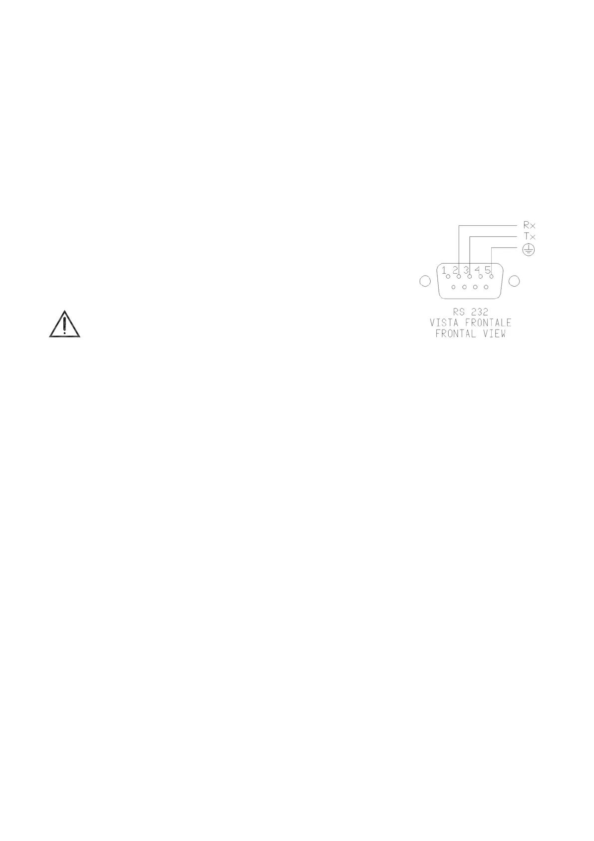
6.4.3 - Serial communication
On the front of the calibrator there is a 9 pole socket (5) connected to the
thermo-regulator, which enables the calibrator to be completely controlled by a
PC (reference to fig.8). The standard adopted RS-232 (contact the technical
department for the communication number).
The external PC must be conform to the IEC950 standard.
7 - MAINTENANCE INSTRUCTIONS
7.1 - Routine inspections instructions
Check that the holes of the calibrator are cleaned, any liquid or oil inside the hole could make oxides or
dirty during the use at high temperature.
Check once a year the calibration date. Frequency of calibration is depending to the use of instrument;
however we suggest to calibrate the instrument every year.
To re-calibrate the instrument is necessary to have a standard temperature instrument, the software
‘CALIBRA’ and follow the instructions of the software or alternately follow the instructions of item 10.1.
8 - SEQUENCE OF MAINTENANCE
Not applicable
Fig.8