Do you have a question about the EK Nucleus AIO CR360 Lux Direct Die D-RGB - 1700 and is the answer not in the manual?
| Model | EK Nucleus AIO CR360 Lux Direct Die D-RGB - 1700 |
|---|---|
| Category | Computer Hardware |
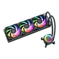
| Radiator Size | 360mm |
| Socket Compatibility | Intel LGA 1700 |
| Lighting | D-RGB |
| Fan Size | 120mm |
| Fan Quantity | 3 |
| Tube Length | 400mm |
| Warranty | 5 years |
| Type | Liquid Cooling System |
| Material | Aluminum |
Procedure to remove the motherboard from the computer case.
Steps to prepare the motherboard before CPU installation.
Removing stock Torx screws from the motherboard using a TX20 Key.
Removing the original mounting mechanism from the motherboard.
Installing the delidded CPU into the motherboard socket.
Cleaning the CPU DIE using a non-abrasive cloth or Q-tip.
Installing the die guard and applying thermal paste to the CPU.
Positioning the protective foam on the CPU to avoid contact with the DIE.
Applying liquid metal paste evenly over the CPU DIE using cotton swabs.
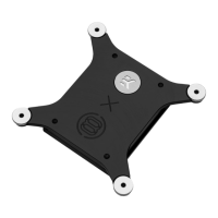
Installing four mounting thumb screws through the motherboard to the backplate.
Assembling the fans to the radiator using UNC 6-32 x 30mm screws.
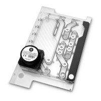
Removing the protective cover from the pump unit's cold-plate.
Installing the Intel bracket onto the pump unit using M3x4 screws.
Applying a small drop of liquid metal to the pump block.
Aligning and fastening the pump unit onto the CPU with mounting screws and thumb nuts.
Mounting the radiator and fan assembly into the PC case using UNC 6-32 x 6mm screws.
Connecting the pump unit's power and RGB cables to the motherboard.
Connecting the pump's 4-pin PWM and 3-pin D-RGB LED connectors to the motherboard.
Connecting fan power and RGB cables.
Connecting the 4-pin fan connector to the motherboard CPU fan header.
Connecting fan D-RGB cables and daisy-chaining multiple fans together.
Orienting the pump top to correctly position the EK logo.