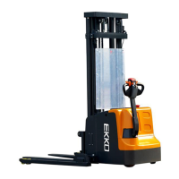
This document describes the EKKO EB18E/EB20E Serial Full Powered Walkie Stacker, a material handling equipment designed for indoor use on smooth, hard, and flat surfaces. It is a walkie-type electric pallet truck with autonomous control, where lifting and lowering are managed via a handle button.
Function Description
The stacker is powered by a battery, which drives an AC motor on the drive wheel and a high-power pump station motor for hydraulic operations. The speed of movement is controlled by frequency conversion of the motor speed, regulated by an accelerator. The primary working part is the fork, used to carry pallets or cargo for transport and short-distance transportation. The expansion of the cylinder, responsible for lifting and lowering the forks, is controlled by buttons on the operating handle, with pressure oil supplied by the pumping station.
The braking system can be activated in several ways:
- Moving the Fahrschalter to position '0'.
- Moving the travel switch directly to the opposite direction, initiating regenerative braking.
- Moving the handle up and down to the braking area ("B"). Releasing the handle automatically moves it to the braking area.
- Activating the "Belly switch" (3) to prevent the operator from being squeezed; this slows down or stops the vehicle if activated behind it.
The brake itself consists of a magnetic yoke assembly, excitation coil, spring, brake disc, armature, gear sleeve, and installation screw. When the excitation coil is energized, it creates a magnetic field that pulls the armature away from the brake disc, allowing the motor to drive the shaft. When power to the coil is cut, the magnetic flux disappears, the armature is released, and the spring presses the armature against the brake disc, generating friction for braking.
Important Technical Specifications
The manual provides specifications for two models: EB18E and EB20E.
| Specification |
EB18E (Imperial) |
EB20E (Imperial) |
| Load Capacity |
3960 lbs |
4400 lbs |
| Max. Lifting Height |
138 in |
177 in |
| Load Center Distance |
24 in |
24 in |
| Fork Length |
45.3 in |
45.3 in |
| Single Fork Width |
4.7 in |
4.7 in |
| Overall Fork Height |
9.8-31.5 in |
9.8-31.5 in |
| Lowered Fork Height |
3 in |
3 in |
| Fixed Leg Length |
42 in |
42 in |
| Adjustable Legs |
45.5-59.1 in |
45.5-59.1 in |
| Turning Radius |
60 in |
60 in |
| Overall Length |
82 in |
82 in |
| Max Overall Width |
61 in |
61 in |
| Extended Mast Height |
154 in |
198 in |
| Lowered Mast Height |
91.3 in |
83.6 in |
| Battery Voltage |
2*12V/150Ah |
24V/210Ah |
| Charger Voltage/Ampere |
24V/20A |
24V/30A |
| Lifting Motor |
3kw |
3kw |
| Lift Speed (laden/unladen) |
92/136 mm/s |
92/136 mm/s |
| Lowering Speed (laden/unladen) |
112/98 mm/s |
112/98 mm/s |
| Driving Motor |
1.5kw |
1.5kw |
| Driving Speed (laden/unladen) |
4.0/4.2 km/h |
4.0/4.2 km/h |
| Service Weight |
2100 lbs |
3014 lbs |
The battery specifications are 2*12V/150Ah for EB18E and 24V/210Ah for EB20E, with corresponding chargers. The battery power indicator displays capacity using ten glowing articles, representing 100% when full. Green indicates 70-100% power, orange 30-60%, and red blinking 0-20%.
Usage Features
The stacker is designed for ease of use with features like:
- Wide View Lifting System: Enhances visibility for the operator.
- DC Controller: A new controller contributes to superior performance.
- Flexible Steering: Allows for easy maneuverability.
- Reliable Braking: Multiple braking mechanisms ensure safety.
- Low Noise and No Pollution: Contributes to a better working environment.
- Emergency Safety Switch: A red button that immediately cuts off power when pressed down. It is pulled up to open the circuit.
- Horn Button: Located in the center of the handle for warning others.
- Battery Capacity Indicator: Displays the remaining battery charge.
Operating Environment:
- Temperature: -10°C to +40°C.
- Gradient: Less than 3%.
- Humidity: Less than 50% at +40°C; higher humidity allowed at lower temperatures.
- Ground: Hard and flat.
- Prohibited Environments: Corrosive, flammable, explosive, or acid-base environments.
- Prohibited Uses: Operating on slopes, lifting or carrying people, or using on lifting/loading ramps.
Starting and Parking Procedure:
- Insert and turn the key switch to the right.
- Pull up the emergency power safety switch to open the control circuit.
- Raise forks approximately 10 cm above the ground.
- Slowly turn the travel switch to achieve the desired speed.
- In case of fault, immediately cut power and press the red emergency power switch down.
- Avoid sudden turns.
- When stopping, lower the fork to the bottom, press the emergency switch down, and remove the key.
Maintenance Features
The manual emphasizes the importance of professional maintenance for safe operation and longevity.
General Maintenance Guidelines:
- Qualified Personnel: Maintenance and service must be performed by special personnel trained by the manufacturer.
- Original Parts: Only original manufacturer's parts should be used for replacements to ensure safety and reliability.
- Environmental Compliance: All oil and fuel replacements must be processed according to local environmental and health laws.
- No Unauthorized Modifications: Any modifications affecting capacity, stability, or safety must be approved by the manufacturer.
Daily Maintenance (9.2):
- Check all poles, cables, and their covers.
- Verify accumulator box security.
- Check for oil leakage.
- Inspect chains, rollers, forks, oil pipes, and horn.
- Check the brake.
- Inspect drive wheels and loading wheels for wear and tear.
Professional Maintenance Manual (9.3):
Maintenance periods are defined based on work hours or time intervals:
- W1: Every 50 work hours, or at least once a week.
- M3: Every 500 work hours, or at least once every three months.
- M6: Every 1000 work hours, or at least once every six months.
- M12: Every 2000 work hours, or at least once every 12 months.
- Trial Run Period (initial 50-100 working hours or two months): Check and tighten wheel nuts, check hydraulic components for leakage, and replace the hydraulic filter.
Specific Component Maintenance:
- Wheels: Quality affects stability; replacement must be approved by the manufacturer and done in pairs.
- Lifting Chain and Rollers: Require periodic lubrication, more frequently in dusty or hot environments.
- Hydraulic Oil Pipe: Must be changed every 6 years, or when hydraulic assembled parts are changed.
- Gearbox: Lubricating oil should be changed every 1000 hours.
Battery Maintenance (9.4.3):
- Keep battery cell nuts dry and clean; tighten terminals and cable ends, and grease to prevent corrosion.
- Ensure good connection between cells; tighten loose pole nuts.
- Keep accumulator surfaces clean and dry; clean spilled acid after recharging.
- Avoid over-recharging, over-discharging, fast charging, and insufficient recharging.
- Do not place conductive objects on the accumulator to prevent short circuits or explosions.
- Ensure clean surfaces when using a densimeter or thermometer.
- Recharge discharged accumulators promptly (within 24 hours).
- For long-term storage, recharge and discharge once a month.
- Add pure water to maintain electrolyte level; do not add electrolyte with specific weight 1.280.
Battery Charging (9.4.8):
- Use the special charger provided.
- Recharge in well-ventilated areas, free of metal objects.
- Check cable connections and connectors for defects.
- Observe all safety instructions for replenishment and recharging.
- Add a protective cover to the truck before using after charging.
Repair Manual (11):
Includes malfunction analysis with common faults (e.g., vehicle not moving, goods not ascending/descending, truck moving slowly) and corresponding processing methods (e.g., checking battery connection, fuses, hydraulic oil, micro switches, controller). Before repair, ensure the vehicle is safely parked, the emergency stop switch is pressed, and the battery connector is unplugged. After maintenance, clean the vehicle and check brake, emergency stop switch, and horn functions.