Do you have a question about the EKKO EB20E and is the answer not in the manual?
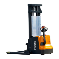
This document provides a comprehensive overview of the EB20E Serial Full Powered Walkie Stacker, an electric pallet truck designed for material handling in warehouses. It details the device's functions, operational procedures, and essential maintenance guidelines to ensure safe and efficient use.
The EB20E stacker is equipped with a wide-view lifting system, a DC controller, and other advanced structures. It features a high-quality motor, traction battery, and a high-power pump station motor, offering superior performance, convenient operation, wide vision, flexible steering, reliable braking, good power performance, reduced noise, and no pollution. Its design emphasizes a good appearance. This stacker is specifically designed for use on smooth ground in warehouses.
The stacker operates using battery power, controlled by electrical and hydraulic systems. It performs actions such as walking, turning, and pallet fork lifting. The lifting and lowering functions are controlled by buttons on the handle. The main working part of the truck is the fork, used to carry pallets or cargo for transport and short-distance transportation. The expansion of the cylinder is controlled by the operating handle, with pressure oil supplied by the pumping station.
The driving system is powered by a battery, controlling an AC motor on the drive wheel. Speed is regulated by frequency conversion control of the motor, managed by the accelerator. The steering system uses the operating handle to drive a rotation direction sensor, which sends turn signals to direct the truck.
The braking system's performance depends on road and vehicle load conditions. Braking can be activated in several ways: moving the Fahrschalter to position '0' to stop the vehicle, moving the travel switch to the opposite direction for regenerative braking, moving the handle up and down to the braking area, or releasing the handle to allow it to automatically move to the braking area. A "Belly switch" is also present to prevent the operator from being squeezed; activating it slows the vehicle or drives it a short distance before stopping. The brake mechanism consists of a magnetic yoke assembly, excitation coil, spring, brake disc, armature, gear sleeve, and installation screw. When the coil is energized, a magnetic field causes the armature to detach from the brake disc, allowing the motor to operate. When the coil is de-energized, the magnetic flux disappears, and the spring presses the armature against the brake disc, generating friction for braking.
The oil pump motor, a DC motor, drives the gear pump to provide hydraulic power for the lifting oil cylinder. The lifting action is controlled by a single-action oil circuit on the valve block, regulated by buttons on the operating handle. The hydraulic system pressure is factory-set and should not be adjusted by unauthorized personnel. The moving truck can only walk without lifting the fork if the battery power is low, indicating an immediate need for charging. The oil pump motor is not designed for continuous long running; lifting movements should have time intervals to prevent overheating or burning. If the oil pump motor starter fails and the motor continues to run, the power supply must be immediately cut off, and the starter replaced.
Before operation, users must familiarize themselves with all switches and buttons on the instrument panel. To start, insert the key into the key switch, turn it right, and pull up the emergency power safety switch to open the control circuit. Forks should be raised about 10 cm above the ground. The travel switch should be engaged slowly to reach the desired speed. In case of any fault during operation, power must be immediately cut off by pressing the red emergency power switch down. Sudden turns while driving should be avoided. When climbing a slope with a full load, operators should be aware of the slope conditions and use the travel switch to maximize grade ability. When parking, the fork should be lowered to the bottom, the emergency switch pressed down, and the key removed.
The emergency safety switch, made of plastic, powers off the truck when pressed down and is reactivated by pulling the red button up. Excessive pressure on this switch should be avoided to prevent damage. A horn button in the center of the handle is used to notify people nearby. The battery capacity indicator displays the remaining battery power.
For handling and stacking operations, when transporting goods, the forklift should approach slowly with the fork parallel to the ground. The fork should be lifted to a height allowing insertion into the freight. After the goods are fully inserted and the truck is parked with brakes applied, the ascend handle is manipulated to lift the load to a certain height, tilting the door frame back. The truck should then slowly reverse, avoiding adjacent goods. Once the weight clears the heap, the goods are lowered to the correct position for handling. When stacking goods, the weight should be lowered, and the door frame tilted back. As the forklift approaches the pile, it should decelerate. Once aligned, apply brakes, adjust the door frame angle to vertical, slightly raise the weight above the pile height, and slowly drive the forklift forward to the pile top. The control lever should be slowly manipulated to drag the weight into the hollow position, ensuring a barrier-free backward position for retreat. After the goods fork out, the weight is reduced, and the door frame is re-entered for the next handling operation.
Maintenance and repair should only be performed by special personnel trained by the manufacturer. All modifications to the vehicle, especially safety devices, and changes to driving speed are prohibited without permission. Only original manufacturer-supplied parts should be used to ensure safety and reliability. Replacement parts, including all oils, must be collected and processed according to local environmental and health laws.
Safety procedures for repair and maintenance include:
Daily maintenance includes checking poles, cables, and their covers, ensuring the accumulator box is secured, checking for oil leakage, inspecting the chain, rollers, fork, oil pipes, and horn, checking the brake, and assessing wear on drive and loading wheels.
Professional maintenance is crucial for safe operation. Maintenance periods are categorized:
Additional operations during the trial run period (initial 50-100 working hours or after two months) include checking and tightening wheel nuts and hydraulic components for leakage, and replacing the hydraulic filter.
Maintenance tasks cover various components:
Battery operations must be performed by qualified professionals in a safe location. Smoking and open flames are prohibited near batteries. Storage and charging areas must be well-ventilated, at least 2 meters from combustible materials, and equipped with fire protection.
Battery maintenance involves:
Worn-out accumulators must be recycled according to local regulations by qualified specialized companies and stored in designated zones. The battery's non-insulated terminal must be protected by an insulating cover. When connecting or replacing the battery, ensure it is securely fixed in the battery box, and the vehicle's power is cut off.
The battery power indicator displays capacity with ten glowing articles representing 100%. As capacity decreases, articles disappear from top to bottom. A red lamp blinks "Energy storage" at 70% discharge, and two lamps blink "run out of battery" at 80% discharge, indicating the need for recharging.
Charging should be done with the supplied special charger in well-ventilated areas, ensuring no metal objects are on the accumulator. All cable connections and connectors should be checked for defects. Safety instructions for replenishment and preparation for recharging must be strictly followed. A protective cover should be added to the truck before use for safety.
A malfunction analysis table helps identify causes and processing methods for common issues like the vehicle not moving, goods not ascending or dropping, inability to stop rising, directional movement issues, slow truck movement, or sudden starts. If problems persist, contact the manufacturer's after-sales service.
Before repair, ensure the vehicle is safely parked, and the emergency stop switch is pressed to unplug the battery connector. Check the hydraulic oil content by opening the electrical box cover, ensuring the fork and frame are lowered to the minimum.
After maintenance, the vehicle can only be used after cleaning, checking normal brake function, normal emergency stop switch function, and proper horn function. Several electromagnetic brake tests should be conducted immediately after maintenance.
| Power Source | Electric |
|---|---|
| Voltage | 48V |
| Power Type | Electric |
| Battery Voltage | 48 V |
| Rated Capacity | 2000 kg |
| Load Center | 500 mm |
| Load Capacity | 2000 kg |
| Lift Height | 3000 mm |
| Travel Speed (loaded/unloaded) | 12/14 km/h |
| Lift Speed (loaded/unloaded) | 0.4/0.5 m/s |
| Lowering Speed (loaded/unloaded) | 0.5/0.6 m/s |
| Mast Height (lowered) | 2000 mm |
| Tire Type | Solid |
| Weight | 2800 kg |