9
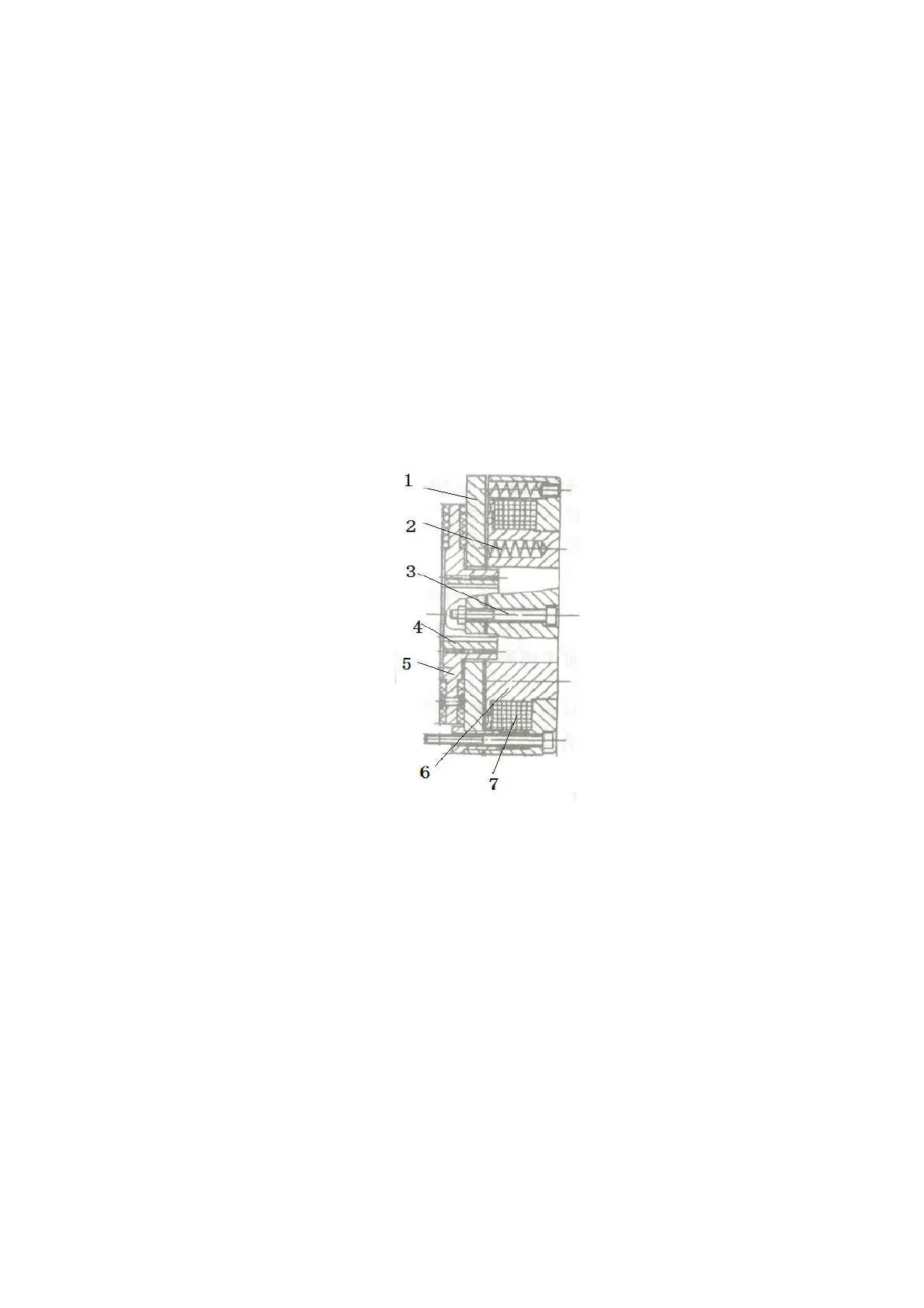
5.3.2Brake operating principle
As shown in the following figure, the brake consists of magnetic yoke assembly 6, excitation coil 7, spring 2, brake
disc 5, armature 1, gear sleeve 4, installation screw 3, etc. The brake is mounted on the end cover of the motor and
the mounting screw is adjusted to the specified air gap value. The gear sleeve is fixed on the shaft, its outer tooth and
the inner tooth of the brake disc cooperate, when the torque is transferred, the brake disc can move axially on the
gear sleeve.
When the actuator coil 7 is energized, the coil produces a magnetic field that causes armature 1 to draw toward the
magnet yoke assembly 6 and armature 1 to detach (release) from the brake disc 5. At this time motor drive shaft
with brake disc 5 start and operate normally. When coil 7 is cut off, the magnetic flux disappears, armature 1 is
released, and spring 2 presses armature 1, and compresses the friction plate on the brake disc, generating friction
force to achieve the purpose of braking.