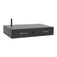
Mount the gSC10 in the desired location
The gSC10 is designed to mount on a shelf or hang in a cabinet
or rack.
Shelf Mounting:
The gSC10 has feet to protect finished surfaces. Set
the gSC10 in a location that will allow you to properly
manage connected wiring so that tension is not placed on the
connections. Wire tension will cause the unit to move and may
cause wires to become disconnected.
Dimension: 17” W x 2.25” H x 14” D
(431.8mm W x 57.2mm H x 355.6mm D)
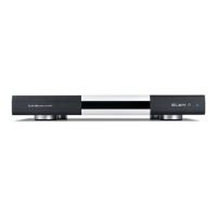
Rack Mounting:
The Rack Mount Brackets included with the gSC10 attach to the
chassis using the included screws.
Do not use longer screws to attach the brackets as this may
permanently damage the gSC10.
Remove the feet from the gSC10 before rack mounting the unit.
When mounting in very warm locations (i.e. enclosed rack or
cabinet) leave a rack space above and/or below the gSC10 for
ventilation.
Dimensions without feet: 1U or 19” W x 1.75” H
(482.6mm W x 44.45mm H)
1
To protect your equipment from power surges and momentary power interruptions we strongly
suggest you utilize a battery-backed power supply (UPS) with this equipment.
ELAN recommends Panamax UPS and power conditioning products for use with your new gSC10.
Unpack the gSC10. Verify that you have all packaging contents.
You should have received:
a. gSC10 f. 1ea RJ-45 to serial DB9
b. 12VDC 2.5A Power Supply female adaptor (P/N 8900598)
c. Rack Mount Brackets g. Relay wiring connector (2 each)
d. 7ea RJ-45 to serial DB9 h. WiFi antenna
male adaptors (P/N 8900597) i. Quick Install Guide (this document)
e. 2ea RJ-45 to serial DB9 female
null modem adaptors (P/N 8900599)
The g! Training Guide contains valuable hardware and software reference documentation and is considered
an important supplement to this document. You would have received the training guide while attending
g!School, however the g! Training Guide is updated regularly. Make sure you have the latest version by visiting
the ELAN Dealer website at www.elanhomesystems.com and following the “dealer” link.
Note: The gSC10 does not have a ViaNET connection. If your installation has devices that require
ViaNET communication you will need to connect an ELAN SC1 to one of the serial RS-232 ports.
www.elanhomesystems.com
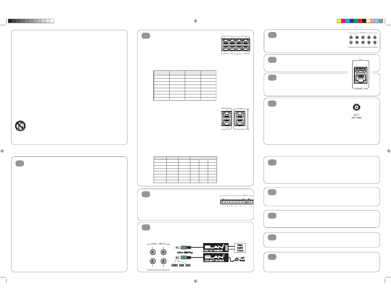
Relay Connections
Ten normally open relays are available for controlling third
party devices. The included removable connectors will
accept up to 16ga bare copper leads. Be careful to verify
that no portion of one wire touches the other wire. Prior to
connection verify that the connected load does not exceed 24volts
AC/DC or 1amp. If either parameter is exceeded, add a higher
capacity relay to control the load and use the gSC10 output to
control that relay.
Sense Input Connections
ELAN sensors can be used to input a status from 3rd party
devices. The status can either be ON or OFF. This can be used to
trigger an event map or as a condition of an event map. Connect
ONLY ELAN sensors to these ports.
3
4
RS-232 Serial Connections
Connect up to 8 RS-232 serial controlled devices using the in-
cluded DB9 to RJ-45 adaptors. Please note that each RS-232
port on the gSC10 supports hardware hand-shaking, which is
required by some 3rd party devices. See the Integration Notes for
the devices you are connecting to determine which DB9 to RJ-45
adaptor should be used and programming specifics. The chart be-
low shows the wiring pin outs for T-568A and T-568B standards
RS-232 wiring pin-outs are as follows:
RS-485 Serial Connections
The two RS-485 ports allow connection to Full Duplex (Aprilaire
for thermostats, for example) and Half Duplex (Pentair Pool
and Spa controllers, for example) RS-485 controlled devices
without using adapters. The table below shows the T-568A
and T-568B color codes and the function of each conductor of
the RS-485 ports. Please refer to the Integration Notes for the
device you are integrating for wiring and programming specifics.
RS-485 wiring pin-outs are as follows:
2
12
13
Software upgrade
Prior to configuring the product, upgrade the gSC10 software to
the latest version of g! Core Module. Core Module can be found
on the ELAN dealer website. The gSC10 is not compatible with g!
Core Module releases prior to g!7.0.
Connecting to the gSC10 on your network
The gSC10 is set from the factory for DHCP networking, which
means it receives its IP address from the network router.
Use g!Tools to find the address and connect to the gSC10.
Power Connection
Once all other connections have been completed, connect the
supplied 12VDC power supply and engage the power switch on
the front of the gSC10.
TEST
The TEST connection is for factory and repair access only.
Do not plug anything into the TEST port. Plugging anything into
the TEST port will void the warranty and release the magic smoke.
10
11
RESET Switch
When pressed momentarily the RESET switch will clear the static IP setup and return the gSC10 to
DHCP as well as reset the WiFi configuration to factory default. When pressed and
held for more than 15 seconds the programming of the current version will be reset to
default. Pressing RESET while applying power will reset the software to the factory version.
WARNING! THIS CANNOT BE UNDONE!!!
9
USB connection
Some accessories may be connected to the gSC10’s USB
connector. Refer to the ELAN Integration Note for the device prior
to connection.
Ethernet Connection
Connect the Ethernet connection to an available 10/100 Mbps
port on the network. This is the preferred connection.
The gSC10 may be powered over Ethernet (PoE).
PoE connection must meet IEEE 802.3at Type 2 requirements
of up to 25W (@50VDC 600mA max).
WiFi Antenna
The gSC10 includes a WiFi radio for installations where
a hardwired Ethernet connection is not available. This flexibility
allows the gSC10 to be used as both an primary
controller and to act as an extender when necessary. Ethernet
connection is preferred, and should always be used when
available. The WiFi radio should be used sparingly and only in
Extender Mode.
The antenna connector is a standard R SMA type
connector. Use only antennas provided with the equipment
or as listed on page 2 of this document. Configuring the WiFi
radio may only be accomplished while the gSC10 is connected to
an Ethernet connection and is covered in the g! Configurator
reference guide.
6
7
8
IR Output Connections
Ten discrete IR outputs are supplied to control third party devices.
The outputs may be configured in g! programming to utilize a
carrier or not. Each output is compatible with Xantech single and
dual emitters.
5
Available ELAN sensors include:
AUDIO, VIDEO, CONTACT CLOSURE,
VOLTAGE, LED/LIGHT, and CURRENT/
MAGNETIC FIELD sensors.
RS-232 Port Pin # 568A Color Code 568B Color Code
1 White/Green White/Orange N/C
2 Green Orange DCD
3 White/Orange White/Green DTR
4 Blue Blue GND
5 White/Blue White/Blue RXD
6 Orange Green TXD
7 White/Brown White/Brown CTS
8 Brown Brown RTS
Function
RS-485 Port Pin # 568A Color Code 568B Color Code Naming Conventions:
1 White/Green White/Orange RxD + RD (B) B+
2 Green Orange RxD - RD (A) B-
3 White/Orange White/Green TxD + TD (B) A+
4 Blue Blue N/C
5 White/Blue White/Blue N/C
6 Orange Green TxD - TD (A) A-
7 White/Brown White/Brown GND GND GND
8 Brown Brown N/C
Use only with the cart, stand, tripod, bracket or table specified by the manufacturer or sold with the apparatus.
When a cart is used, use caution when moving the cart/apparatus combination to avoid injury from tip-over.
9901335_ELAN_QuickGuide_gSC10_ENG_CHI_0314_PRINT.indd 4 3/14/14 3:44 PM
 Loading...