EasyManua.ls Logo

ELAUT Benchmark Games Fireball - User Manual

ELAUT Benchmark Games Fireball
25 pages
Print Icon
To Next Page IconTo Next Page
Loading...
0
888-583-1000
TEL: (561)588-5200
Fax: (561)493-2999
Customer Service: (561)253-3311
www.benchmarkgames.com
51 Hypoluxo Road
Hypoluxo, FL 33462
166MAN001
Question and Answer IconNeed help?

Do you have a question about the ELAUT Benchmark Games Fireball and is the answer not in the manual?

Summary

Manual Revision Log

Fireball Game Physical Components

Header;Marquee

Illuminated top sign displaying game name and branding.

Ball Drop Assembly

Mechanism responsible for releasing balls onto the playfield.

Bonus;Credit Displays

Digital screens showing current credits and bonus values.

Ball Lift Belt

System of belts used for internal ball movement.

Playfield Wheel

The rotating wheel where balls land for scoring.

Button;Coin Tower

Controls for player input and coin insertion.

Ticket Door

Access point for dispensing game tickets.

Game Setup and Initial Configuration

Unloading and Assembly

Instructions for unpacking and initial setup of the game.

Game Play Sequence and Behavior

Explanation of game flow, credit addition, and player actions.

Payout Wheel Configurations and Adjustments

Table 1: Dollar Wheel Payouts

Payout wheel configuration for the dollar denomination.

Table 2: 25 Cent Standard Payouts

Standard payout wheel configuration for 25 cent denomination.

Table 3: 50 Cent Payouts

Payout wheel configuration for the 50 cent denomination.

Table 4: Custom Payouts

Payout wheel configuration for custom setups.

Game Programming Options Access

Accessing and Navigating Program Mode

Guide on entering and navigating the game's programming menu.

Fireball Game Configuration Menu Navigation

Configuration Menu Overview

Overview of menu items for game settings, tests, and exits.

Technical Operation of Game Mechanisms

Ball Drop Operation

Explanation of the ball drop solenoid and plunger mechanism.

Wheel Location and Ball Scoring

How wheel position and optics determine game scores.

Ball Lift Operation

Explanation of the ball lift motor and belt system.

Main Electronic Components Identification

Circuit Board Location

Illustration showing the physical placement of electronic boards within the game.

Core Electronic Components Identification

Main CPU Board

The primary controller board for game actions.

Quad Stepper Controller Board

Board handling motor movements for wheel and ball lift.

LED RGB Controller Board

Board controlling the game's LED lighting system.

Power Distribution and Metering Components

Power Distribution Board

Board distributing power to main, light, and quad boards.

Coins In;Tickets Out Meter

Meters tracking coins entered and tickets dispensed.

Display and Ticket Dispenser Components

Bonus 4 Digit Display

Display showing the bonus value to be won.

Credit;Ball Count 2 Digit Display

Display showing credits or balls accumulated.

Triple Ticket Dispenser

Mechanism that dispenses tickets to players.

Scoring Sensor Components

Scoring Opto Receiver

Receives signals from the transmitter to score balls.

Scoring Opto Transmitter

Sends a steady beam for the receiver to detect.

Home Opto Sensor

Detects the wheel's zero position using a pin.

Troubleshooting: Error Codes and Solutions

E-1: General RS485 Communication Error

Diagnosing and resolving RS485 communication disruptions.

E-2: Ball Lift Jammed

Identifying and fixing issues with the ball lift mechanism.

E-3: Game is Out of Tickets

Troubleshooting guide for when the ticket dispenser is empty.

E-4;E-11;E-13: Quad Stepper Communication Error

Troubleshooting for communication errors between boards.

E-5: Bonus Display Communication Error

Troubleshooting bonus display communication issues.

E-6: Credit Display Communication Error

Troubleshooting credit display communication problems.

E-7: LED RGB Communication Error

Troubleshooting errors with LED RGB light board communication.

E-8: SD-Card Read

Troubleshooting issues with SD card reading or corruption.

E-9: EEPROM R;W Failure

Troubleshooting EEPROM read/write errors.

E-10;E-12: Wheel Home Position Error

Diagnosing and fixing wheel home position errors.

E-14 - E-16: Main Board Software Errors

Troubleshooting main board software faults.

Reset Game

Procedure for resetting the game to default settings.

Customer Service

Contact information for ordering parts or support.

Electronic Board Pinout Diagrams

Main Board Pinouts

Pin definitions for Main Board connectors J3, J5, J4.

RGB LED Controller Board Pinouts

Pin definitions for RGB LED Controller Board connectors.

Quad Stepper Controller Board Pinouts

Pin definitions for Quad Stepper Controller Board connectors.

Key Game Component Parts

Balls

Details on the number of balls required and replacement recommendations.

Drive Belt

Description of the small belt connecting the ball lift motor.

Ball Lift Belt Assembly

Description of the elevator belt for ball transport.

Other Game Component Assemblies

Blue Roller for Motor

Description of the rubber roller for the playfield motor.

Roller Bearing Assembly for Wheel

Description of the bearing assembly for the playfield wheel.

Playfield Motor Assembly

Description of the motor that spins the playfield wheel.

Ball Lift Motor Assembly

Description of the motor for the ball lift belt.

Overview

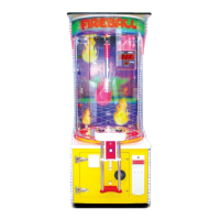
The Fireball arcade game is a coin-operated redemption game designed to provide an engaging and rewarding experience for players. Manufactured by Benchmark Games, a member of the ELAUT Group, it features a vibrant and interactive design, with a focus on ball-dropping mechanics and ticket payouts.

Function Description:

The core function of the Fireball game is to allow players to drop a ball onto a spinning playfield wheel, aiming for specific holes that correspond to ticket payouts or a bonus. The game operates in several modes:

  • Power-Up Initialization: Upon powering on, the game initiates a sequence where the wheel spins, displays light up, and the ball lift system runs to ensure the ball trough is filled.
  • Attraction Mode: When not in active play, the game enters an attraction mode, triggering various lights and sounds at a programmable frequency to entice players.
  • Adding Money: Players insert coins or bills to add credits. A "coin-in" or "bill-in" sound confirms the transaction, and the current credit value is shown on the Credit display. Once enough money is added for a credit, the game transitions to Play Mode.
  • Play Mode: In Play Mode, play sounds begin, and the play buttons flash, indicating readiness for player interaction.
  • Player Interaction: The player presses a "Stop Wheel" button to slow and momentarily stop the wheel, followed by a "Drop Ball" button to release a ball onto the playfield. Simultaneously, the ball lift system activates to replenish the played ball, stopping once the ball trough is full.
  • Scoring/Payout: When the ball drops into a hole on the wheel, the game senses its position using optical sensors. Based on the hole the ball lands in, the game pays out the appropriate number of tickets. A light and sound celebration occurs for bonus hits or standard wins. If the player has remaining credits, the game continues in Play Mode; otherwise, it returns to Attraction Mode.

Important Technical Specifications:

Basic Components:

  • Header/Marquee: The top illuminated sign displaying the game title.
  • Ball Drop Assembly: The mechanism at the top where balls are released.
  • Bonus/Credit Displays: Digital displays showing the current bonus value and player credits.
  • Ball Lift Belt: A belt system that transports balls from the lower cabinet to the ball drop assembly.
  • Playfield Wheel: The spinning circular surface where the ball lands to determine payouts.
  • Button/Coin Tower: The player interface for inserting coins and pressing game buttons.
  • Ticket Door: The exit point for dispensed tickets.

Main Electronic Components:

  • Main CPU Board (Part Number: 166PCB001): The central controller located in the lower cabinet on the left. It manages game actions, commands, and overall game logic. ID Switch Setting: 0100 (On, Off, Off, Off).
  • Quad Stepper Controller Board (Part Number: PCB00068): Located in the lower cabinet on the left, this board controls the stepper motors for the wheel and ball lift. ID Switch Setting: 0000 (All Off).
  • LED RGB Controller Board (Part Number: PCB00086): Located in the lower cabinet on the right, this board controls the lighting effects, specifically the lights behind the ball drop section and along the sides of the game. ID Switch Setting: 0000 (All Off).
  • Power Distribution Board (Part Number: PCB00032): Located in the lower cabinet on the left, this board supplies power to the main board, light board, quad board, and various lights. ID Switch Setting: None.
  • Coins In/Tickets Out Meter (Part Number: 500ASM024): Located on the floor of the lower cabinet, these meters track the number of coins inserted and tickets paid out.
  • Bonus 4 Digit Display (Part Number: PCB00120): Located on the back wall, top right, above the credit display. Shows the bonus value. ID Switch Setting: 0000 (All Off).
  • Credit/Ball Count 2 Digit Display (Part Number: PCB00003): Located on the back wall, top right, below the Bonus display. Shows current credits or plays. ID Switch Setting: 1000 (On, Off, Off, Off).
  • Triple Ticket Dispenser (Part Number: 112ASM001): Located in the lower cabinet behind the white plastic bezel. Dispenses tickets. ID Switch Setting: 0000 (Off, Off, Off, Off).
  • Scoring Opto Receiver (Part Number: PCB00025): Under the playfield wheel, toward the back. Receives signals from the transmitter to score the ball.
  • Scoring Opto Transmitter (Part Number: PCB00029): Under the playfield wheel, toward the back. Sends a steady beam to the receiver.
  • Home Opto Sensor (Part Number: PCB00077): Under the playfield wheel, toward the front right. Reads a pin on the wheel to signal the zero position to the main board.

Game Components:

  • Balls (Part Number: 115BLL001): The game requires 7 balls at any given time.
  • Drive Belt (Part Number: BLT10011): A small belt in the back of the cabinet connecting the Ball Lift motor to the pulley system.
  • Ball Lift Belt Assembly (Part Number: 115ASM017): The elevator belt that carries balls from the cabinet to the top of the game.
  • Blue Roller for Motor (Part Number: GEN00169): A rubber roller that sits on the playfield motor and spins the large playfield wheel.
  • Roller Bearing Assembly for Wheel (Part Number: 115ASM016): Supports the playfield wheel.
  • Playfield Motor Assembly (Part Number: 500ASM127): Spins the playfield wheel.
  • Ball Lift Motor Assembly (Part Number: TBA): Spins the small belt attached to the Ball Lift Belt to move balls up the game.

Usage Features:

  • Programmable Settings: The game offers extensive programming options accessible via "Back," "Program," and "Next" buttons on the Power Distribution Board. These settings include:
    • Game Volume, Attraction Volume, Bonus Round Volume: Adjustable from 0 to 255.
    • Pulse Per Credits: 1 to 8.
    • Play per credit: 1 to 8.
    • Two Cents Tickets: Yes/No option.
    • Bonus Start Value: Range 50 to 9940 (display value x 10).
    • Bonus Max Value: Range "Bonus start value + 50" to 9990 (display value x 10).
    • Bonus Increments: 0 to 4.
    • Game Brightness: 0 to 15.
    • Payout Settings: 1 to 5.
    • Wheel Speed: 1 to 4 (Slow, Medium, High, Dynamic Speed).
  • Test Mode: Includes tests for Upper Wheel Scoring, Lower Wheel Scoring, Ball Drop, and Ticket Dispenser to aid in troubleshooting and calibration.
  • Wheel Options: Various wheel configurations are available (Dollar Wheel, 25 Cent - Standard, 50 Cent, 25 Cent 2 Point) to allow for custom payout structures based on location and desired revenue. The manual recommends using default factory settings as a starting point.

Maintenance Features:

  • Error Codes and Troubleshooting Guide: The manual provides a comprehensive list of error codes (E-1 to E-16) with detailed troubleshooting steps. These include:
    • E-1: General RS485 Communication Error: Checks for cold solder joints, missing plugs, proper wire connections, and continuity on blue and gray wires.
    • E-2: Ball Lift Jammed: Checks for physical jams in the ball catch, lift belt, or drop assembly, and verifies the Ball Alert Switch, Quad Stepper Board signal, and motor for damage.
    • E-3: Game is Out of Tickets: Checks ticket bins and dispenser loading.
    • E-4/E-11/E-13: Quad Stepper Communication Error/Wheel Stepper Communication error: Similar to E-1, focusing on the Quad Stepper Board, including power checks (VCC and CPU lights) and voltage measurements on the J3 Connector.
    • E-5: Bonus Display Communication Error: Checks connections and continuity for the 4-digit Bonus Display Board.
    • E-6: Credit Display Communication Error: Checks connections and continuity for the 2-digit Credit Display Board.
    • E-7: LED RGB Communication Error: Checks connections and continuity for the LED RGB Light Board, including power checks and voltage measurements on the J6 Connector.
    • E-8: SD-Card Read: Checks for SD card reseating, corrupt files, and power to the Main board (3.3V and CPU lights, voltage on J1 Connector).
    • E-9: EEPROM R/W Failure: Checks power to the Main board (3.3V and CPU lights, voltage on J1 Connector).
    • E-10/E-12: Wheel Home Position Error: Checks power to the Main board (VCC and sensor lights), voltage on the connector, and signal wire continuity and voltage (should be a steady 5V, dropping to 0V when obstructed). Also checks signal at the Quad Stepper.
    • E-14 - E-16: Main Board Software Errors: Suggests turning the game off and on, entering programming mode, selecting "Exit," and choosing "Restore Game Default" (which resets all settings to factory standards).
  • Physical Damage Checks: For most errors, the guide recommends checking for any physical damage on boards and harnesses.
  • Ball Replacement Recommendation: It is recommended to change the game balls every 6-9 months, depending on game usage, to ensure optimal performance.
  • Customer Service: A dedicated customer service line is available for ordering parts or persistent errors, operating Monday-Friday from 9:00 am to 5:00 pm EST.

ELAUT Benchmark Games Fireball Specifications

General IconGeneral
BrandELAUT
ModelBenchmark Games Fireball
CategoryArcade Game Machines
LanguageEnglish

Related product manuals