1
Appendix E, Troubleshooting
General Troubleshooting Procedure
Look for your problem in the Troubleshooting Tables.
Closely examine PC boards for poor solder joints and incorrect, broken or
missing components.
Follow the step-by-step receiver and transmitter Signal Tracing
procedures at the end of this section.
Check voltages using the DC Voltage Table at the end of this section.
Error Messages
If you see a message such as E 3 0 on the LCD, look up the corresponding
entry in the Troubleshooting Tables. Error messages can usually be cleared by
pressing any switch. However, the cause of the message should be investigated
before continuing to operate the transceiver.
Troubleshooting Tables
There are five troubleshooting tables (listed below). Within each table,
problems are identified by 2-digit numbers for cross-referencing purposes. In
most cases you’ll know which table to look in based on the symptoms you
observe. If in doubt, start with the General Troubleshooting table. Some
problem identifiers have corresponding error messages (see above).
General Troubleshooting 00-19
Display and Control Circuits 20-39
VFO and Premixer 40-59
Receiver 60-79
Transmitter and Keyer 80-99
Note: Components are identified by their PC board and reference designator.
For example, "FP-U1" means U1 on the Front Panel board.
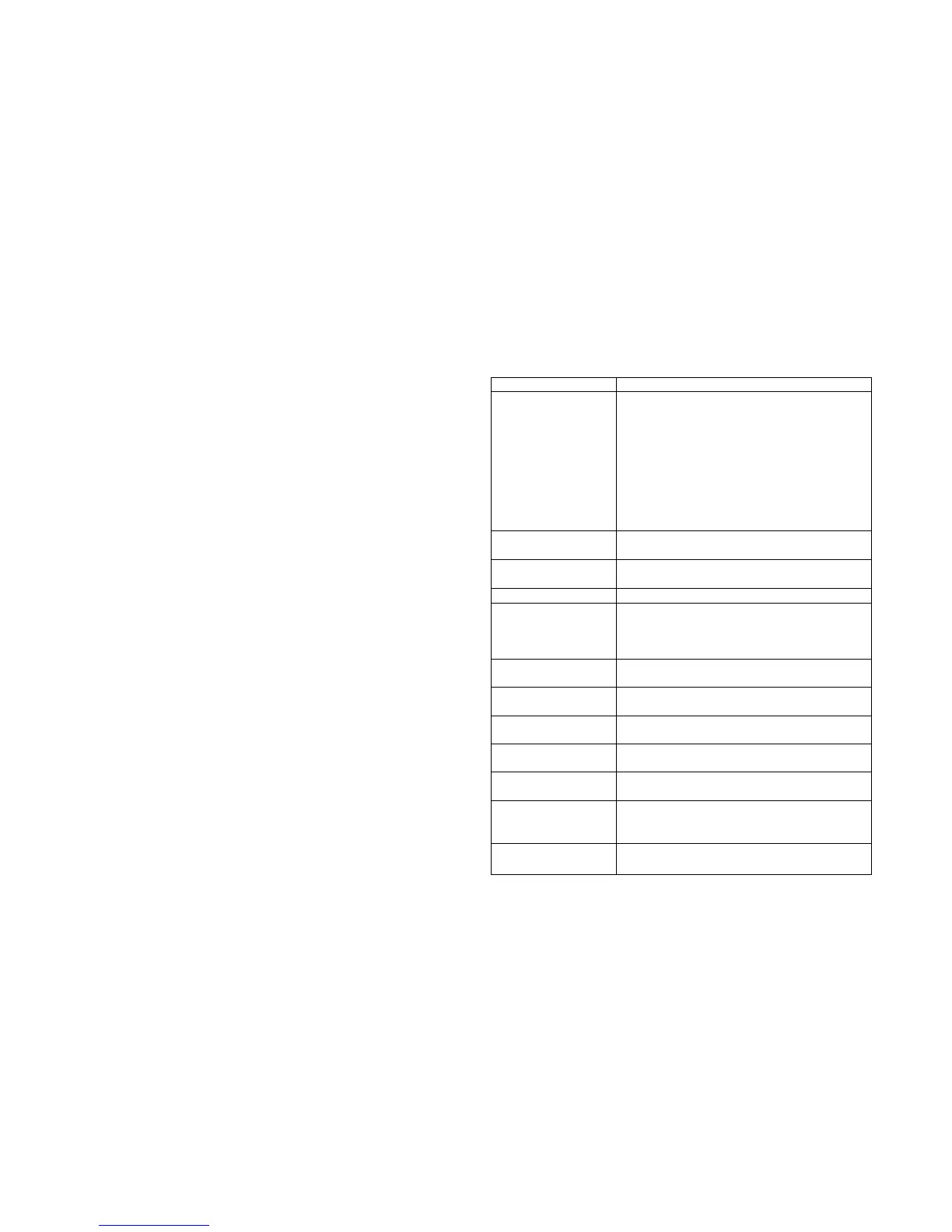
General Troubleshooting (00-19)
Problem Troubleshooting Steps
00 Unit appears to be
completely dead when
power switch is turned
on (no display, no
audio); possible
smoke, hot
components, etc.
Make sure your power supply is connected,
turned on, and not plugged in backwards
Check fuses; examine cables for open/short
Check resistance to ground on 12V, 8V, and
6V lines; check for RF-Q7 tab short
Verify front panel and filter boards are
plugged in, with connectors fully seated
Measure the +6V and +8V regulated power
supplies (20)
Check the MCU, FP-U1 (26)
01 LCD or LED
problem
See control circuits (24)
02 B A T L O
displayed
Battery voltage may be below 9 V. Recharge
the battery as soon as possible.
03 No audio See Receiver troubleshooting table (60)
04 Switches or
potentiometers do not
function correctly or
are intermittent
Front panel board may not be plugged in
Check the MCU (26)
Check all regulated supply voltages (20)
Check switches and related components (21)
05 Current drain is
excessive on receive
Check regulated voltages (20); look for a
component that’s warm to the touch
06 Supply voltage
drops when K1 is on
Check receive-mode current drain (05)
Battery not fully charged
07 Error in actual vs.
displayed frequency
See Operation section (VFO Calibration)
08 Freq. drift or
instability
See VFO troubleshooting table (40)
09 EEPROM init
is pending
See Advanced Operating Features,
Resetting to Factory Defaults (page 57)
10 EEPROM was
just initialized
You may see
E 1 0 one time on power-up, or
if you install a new version of the firmware.
All K1 parameters are set to defaults.
15 E N D or P = 0 is
displayed on keydown
E N D : TX out of range (see specifications)
P = 0 : TX disabled via O U T menu entry