ELECRAFT 15
Install the diodes listed below, beginning with D1, which is in
the upper left-hand corner of the PC board. (Refer to the parts list
if necessary to identify the different types of diodes.) If a diode has
only one band, the end with the band (the cathode) should be
oriented toward the banded end of the corresponding PC board
outline. If a diode has multiple bands, the widest band indicates the
cathode end.
__ D1, 1N4148 __ D2, 1N4148 __ D3, 1N5817
Double-check the orientation of the diodes, then solder.
Install the small fixed capacitors listed below, beginning with
C2 in the upper left-hand corner of the board. (This list includes all
of the fixed capacitors on the Control board except the tall,
cylindrical electrolytic types, which will be installed later.) The list
shows both the value and the capacitor labels, using notation
explained in the previous section. After installing each capacitor,
bend the leads outward to hold it in place, but do not solder.
Note: Remember to complete all items in each line before moving
on to the next. (Install C2, C3, and C4, then C7, etc.)
__ C2, .001 (102) ⇒ __ C3, .01 (103) ⇒ __ C4, 0.47 (474)
__ C7, 330 (331) __ C6, .047 (473) __ C8, 39 (39)
__ C9, .01 (103) __ C10, .01 (103) __ C12, .0027 (272)
__ C5, .01 (103) __ C14, .047 (473) __ C17, .01 (103)
__ C42, 0.1 (104) __ C16, .047 (473) __ C11, .01 (103)
__ C19, .047 (473) __ C21, 33 (33)
__ C23, .01 (103) __ C20, .001 (102) __ C18, .01 (103)
__ C43, .001 (102) __ C27, .022 (223) __ C25, 0.1 (104)
__ C26, 0.1 (104) __ C24, .0027 (272) __ C31, .047 (473)
__ C34, .001 (102) __ C30, .047 (473) __ C40, .01 (103)
__ C35, .01 (103) __ C36, .0027 (272) __ C39, .01 (103)
__ C41, .01 (103) __ C37, .01 (103) __ C38, 680 (681)
Solder all of the small fixed capacitors.
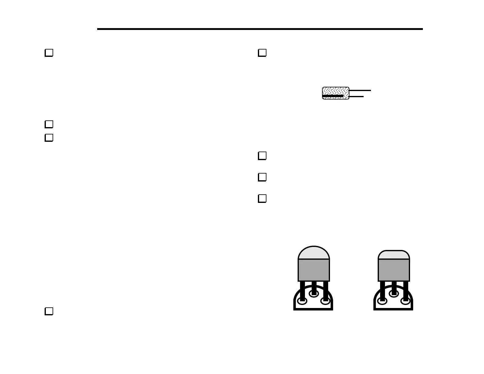
Install and solder the electrolytic capacitors listed below,
which are polarized. Be sure that the (+) lead is installed in the hole
marked with a "+" symbol. The (+) lead is usually longer than the
(–) lead, and the (–) lead is identified by a black stripe (Figure 4-1).
-
Figure 4-1
__ C1, 2.2 µF ⇒ __ C13, 22 µF ⇒ __ C15, 100 µF
__ C28, 220 µF __ C29, 220 µF __ C33, 2.2 µF
__ C32, 22 µF
Install and solder ceramic trimmer capacitor C22. Orient the
flat side of this trimmer as shown on its PC board outline.
Using a small flat-blade screwdriver, set C22 so that its
screwdriver slot is parallel to the outline of nearby crystal X2.
Locate Q12 (type PN2222A), which is a small, black TO-92
package transistor. Q12 and other TO-92 transistors may have
either of the two shapes shown in Figure 4-2. The large flat side
of the device must be aligned with the flat side of the
component outline. The part number may be found on either
side.
Figure 4-2