16 ELECRAFT
Install Q12 near the upper left-hand corner of the PC board.
Align the large flat side of Q12 with its PC board outline as in
Figure 4-2. The body of the transistor should be about 1/8" (3 mm)
above the board; don’t force it down too far or you may break the
leads. Bend the leads of the transistor outward slightly on the
bottom to hold it in place. Solder Q12.
Install the remaining TO-92 package transistors in the order
listed below.
__ Q11, PN2222A ⇒ __ Q1, 2N3906 ⇒ __ Q2, 2N3906
__ Q3, 2N7000 __ Q4, 2N7000 __ Q5, 2N7000
__ Q6, J310 __ Q7, J310 __ Q8, PN2222A
__ Q9, MPS5179 __ Q10, MPS5179
Solder and trim the leads of these transistors.
Install crystals X1 and X2 so that they are flat against the
board. X1 is 5.068 MHz and is located near the notch in the lower
left-hand corner. X2 is 4.000 MHz, and is located near the center
of the board.
Solder the crystals.
Prepare two 3/4" (19 mm) jumpers wires from discarded
component leads. These short jumpers will be used to ground the
crystal cans in the next step.
i
Grounding the crystal cans in the following step is required
to ensure proper crystal oscillator performance.
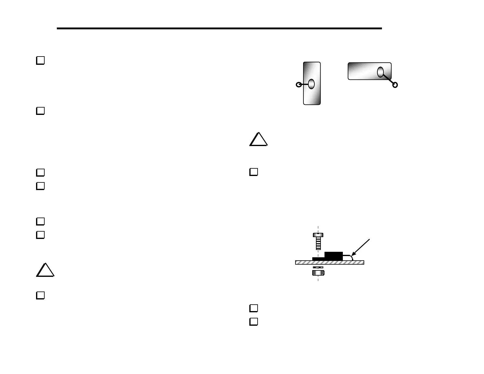
Referring to Figure 4-3, insert the jumper wires into the
grounding holes provided near X1 and X2. Fold each wire over the
top of the crystal and solder it to the top of the can. (Only a small
amount of solder is required.) Then solder and trim the wire on the
bottom of the board.
1
2
Figure 4-3
i
The voltage regulators, U4 and U5, will be installed in the
following steps. These regulators have different voltages and must
not be interchanged. Check the labels before soldering.
Install U4 (LM2930T-8) and U5 (78M05, 7805T, L7805,
etc.), forming the leads as indicated (Figure 4-4). Fold the pins over
the shaft of a small screwdriver to create smooth bends. After
inserting the leads into the proper holes, secure each IC with a 4-40
x 3/8" (9.5 mm) machine screw, #4 lock washer, and 4-40 nut.
(These regulators may have either plastic or metal mounting tabs.)
Use smooth
bend, not sharp
Figure 4-4
Solder the voltage regulator ICs.
Trim the IC leads as close to the PC board as possible.