ELECRAFT 17
Install a 40-pin IC socket at U6. (The microcontroller will be
inserted into the socket in a later step.) Orient the notched end of
the socket to the left as shown on the PC board outline. Bend two
of the socket’s diagonal corner leads slightly to hold the socket in
place, then solder only these two pins. If the socket does not
appear to be seated flat on the PC board, reheat the solder joints
one at a time while pressing on the socket.
Solder the remaining pins of the 40-pin socket.
i
The connectors used in the following steps have plastic
bodies that can may melt if too much heat is applied during
soldering, causing the pins to be mis-positioned. Limit soldering
time for each pin to 3 seconds maximum (1 to 2 seconds should be
adequate).
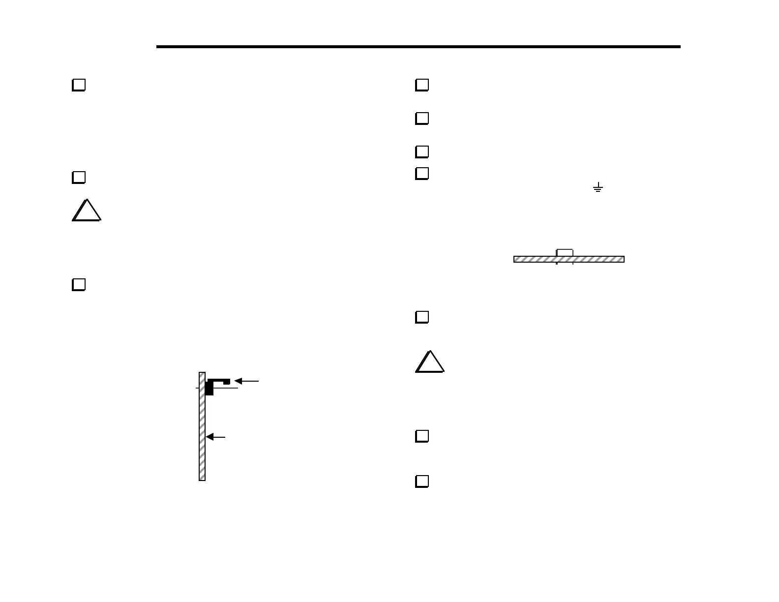
Install the 2-pin male connectors, P5 and P6. As shown in
Figure 4-5, the polarizing tab on each connector should be closest
to the top edge of the board. P5, the voltmeter input connector,
can be found near the upper left-hand corner of the board. P6 is
used for frequency counter input, which is in the upper right-hand
corner.
Locking
Tab
op side of
C Board
Figure 4-5
Install the 10-pin, dual-row connector, P4. It is located to the
left of P5. It must be seated flat on the board before soldering.
Install P7, a 3-pin male connector, to the right of P5. The
short ends of the 3 pins are inserted into the board.
Install a shorting jumper onto the two right-hand pins of P7.
At the upper left and right corners of the board are short
jumpers, labeled with ground symbols (
). Use discarded
component leads to make 3/4" (19 mm) U-shaped wires for each
jumper (Figure 4-6). Solder the jumpers on the bottom of the board,
with the top of the U-shape approx. 1/4" (6 mm) above the board.
Figure 4-6
Locate the outlines for resistors R18 and R19 on the bottom
side of the Control board.
i
The pads used for R18 and R19 are shared with connectors
J1 and J2, which are labeled on the top side of the board. These
connectors are provided with the KAF2 audio filter option. You
should not install J1 and J2 or the KAF2 option until after K2
assembly and checkout have been completed.
Install short wire jumpers at R18 and R19. Make the jumpers
from discarded component leads as you did above, but keep them
flat against the board. Solder the jumpers on the top side.
Install the following resistors on the bottom side of the board:
__ R12, 820 (GRY-RED-BRN) __ R11, 47 k (YEL-VIO-ORG)