18 ELECRAFT
i
The connectors along the bottom edge of the board (P1,
P2 and P3) will be installed next. It is very difficult to remove them
once they are soldered. Follow all instructions carefully.
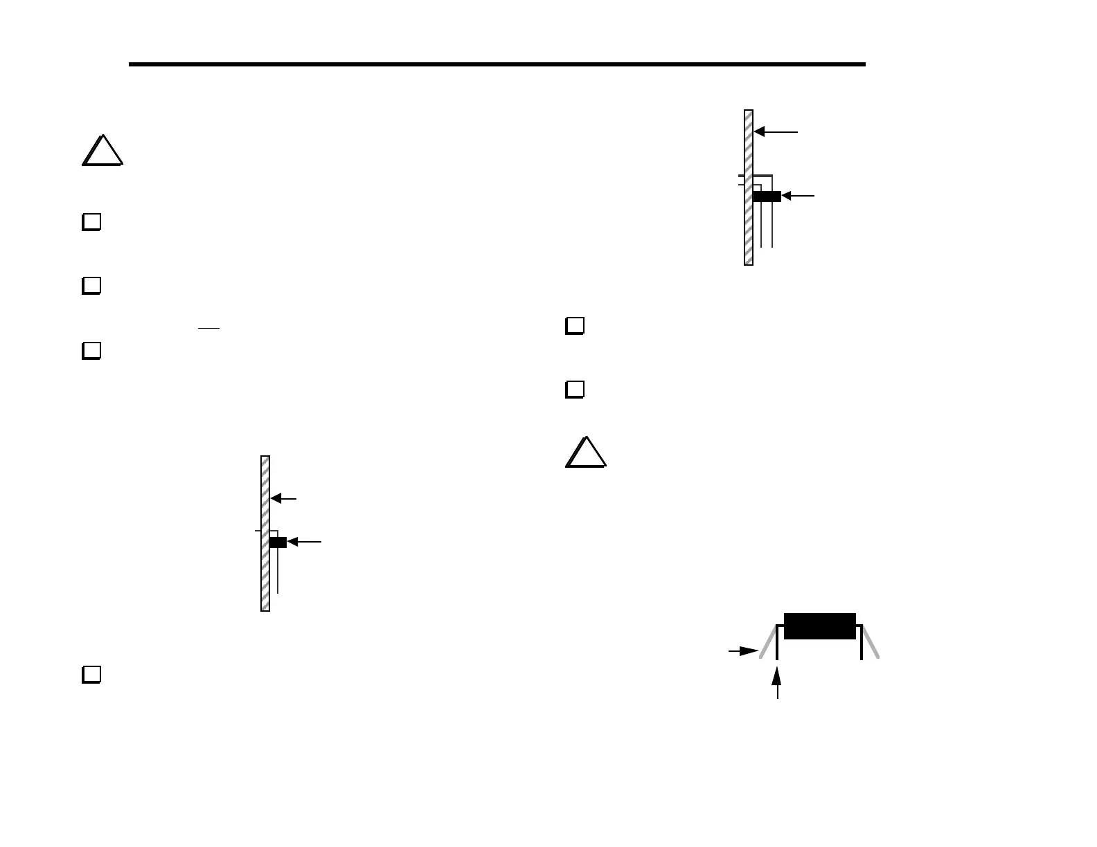
Hold the Control board vertically as shown in the side view
below (Figure 4-7). The top side of the board--the side with most of
the components--should be to the right.
Turn to page 8 and review Figure 3-3, which shows how the
Control board plugs into the RF board. P1, P2, and P3 will all be
installed on the top side of the Control board as shown.
Position 6-pin right-angle connector P1 as shown in the side
view below (Figure 4-7). Do not solder P1 until the next step.
The plastic part of the connector must be seated flat against the PC
board, and the pins must be parallel to the board. Do not bend or
trim the pins on the bottom of the board.
Top side of
PC Board
P1
Figure 4-7
Solder just the two end pins of P1, then examine the placement
of the connector. If P1 is not flat against the board, re-heat the
solder on the end pins one at a time while pressing firmly on the
connector. Once it is in the right position, solder all pins. Do not
trim the leads.
op side of
C Board
3
Figure 4-8
Install P3, the 20-pin, dual-row right-angle connector (Figure
4-8). Use the same method you used for P1. Do not solder P3 until
you are sure that it is seated properly.
Install P2, the 36-pin, dual-row, right-angle connector. Use the
same method you used for P1 and P3.
i
When you install ICs in the following steps, always
straighten the leads of each IC first as shown in Figure 4-9. The two
rows of pins must be straight and parallel to each other to establish
the proper pin spacing for insertion into the PC board or socket.
To straighten the pins, rest one entire row of pins against a hard,
flat surface. Press down gently on the other row of pins and rock
the IC forward to bend the pins into position as shown below.
Straight
Flared
Figure 4-9