ELECRAFT 19
i
Before handling any IC, touch an unpainted,
grounded metal surface or put on a conductive wrist-strap.
Locate U2, an 8-pin IC, part number LM833. (LM833 is the
basic part number. There may be an additional prefix or suffix or
other markings.) This and all remaining ICs on the Control board
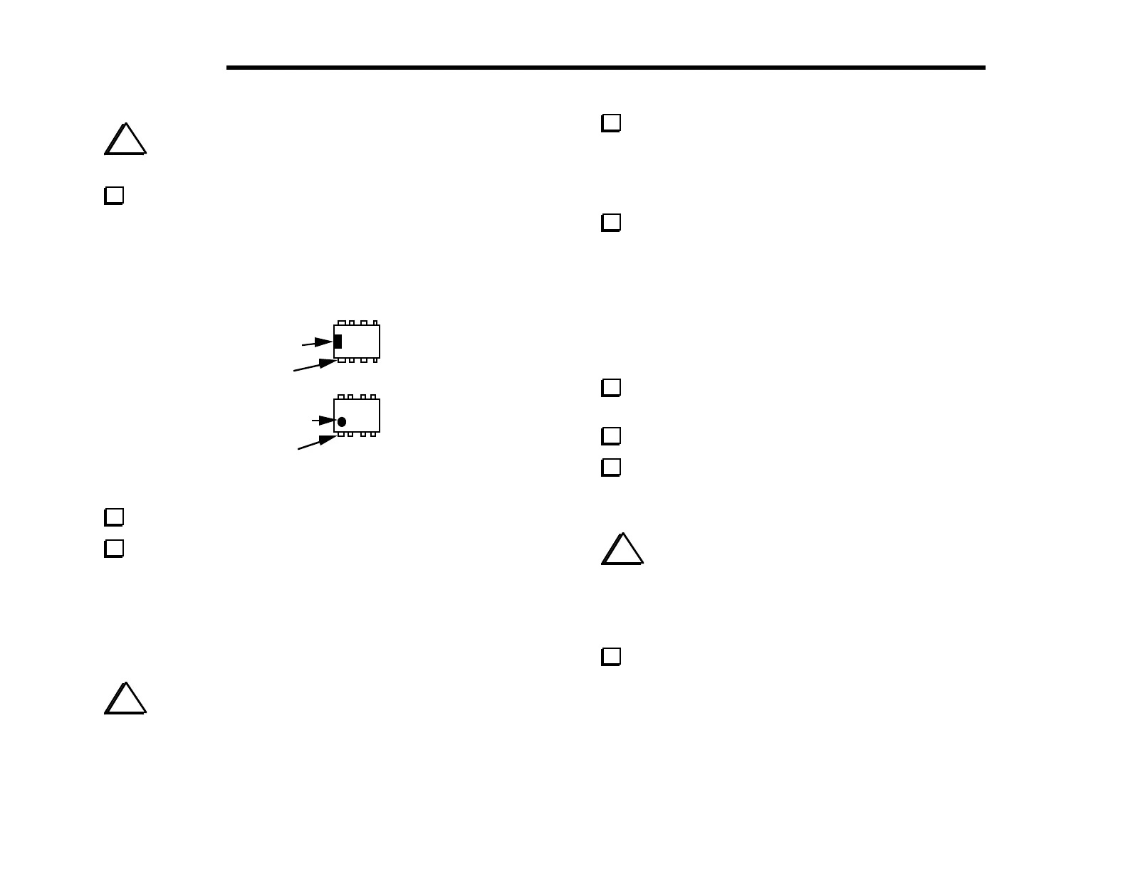
are Dual-Inline Packages, or DIPs. Referring to Figure 4-10,
identify the notched or dimpled end of the IC. IC pins are counted
starting from pin 1 (as shown below) and going counter-clockwise.
Pin 1
Notch
Pin 1
imple
Figure 4-10
Straighten the leads of U2 (see Figure 4-9).
Install U2 in the orientation shown by its PC board outline,
near the upper left-hand corner of the PC board, but do not solder
it yet. Make sure the notched or dimpled end is lined up with the
notched end of the PC board outline. Even though the outline is
covered when the IC is installed, you can still verify that the IC is
installed correctly by looking at pin 1. The PC board pad
corresponding to pin 1 will be either oval or round.
i
You may overheat the IC pins or PC pads if you take an
excessive length of time to solder. After a few tries, you should be
able to solder an IC pin in about 1 or 2 seconds.
Bend two of U2’s corner pins out slightly on the bottom of
the board to hold the IC firmly in place, flat against the top of the
board. Find pin 1 and verify that its pad is either round or oval.
Once U2 is properly seated, solder all eight pins, using a minimum
of solder.
Install the ICs listed below. Bend the pins to hold each IC in
place as you did with U2, but do not solder until the next step. The
notched or dimpled end of each IC must be aligned with the notched
end of its PC board outline.
Note: For U1, the IC type supplied may be either NE602 or SA602.
__ U1, NE602 __ U3, LM6482 __ U7, 25LC320
__ U8, MAX534 __ U9, LM380 __ U10, LMC660
Check the orientation of pin 1 on each IC by looking at the
associated PC board pads, as before. Then solder all of the ICs.
Locate the microcontroller, U6.
Straighten the pins of U6 (see Figure 4-9). With a large IC such
as this, you can hold the IC body at both ends as you re-form each
row of pins.
i
When the microcontroller is pressed in its socket, you must
be careful to avoid jamming its pins. Make sure that all pins are
lined up with the associated holes in the socket before pressing
down on the IC. Watch the pins on both rows as you press down,
re-aligning them with the socket holes individually if necessary.
Insert the microcontroller, U6, into its socket. Make sure that
pin 1 on the IC itself is lined up with the pin 1 label near the lower
left-hand corner of the PCB outline. Note: The revision label on
the IC (usually white) may not be oriented the same direction as the
text printed on the IC. Do not use the label as a guide--use the
notch or dimple to identify pin 1.
 Loading...


