20 ELECRAFT
Option Components
All component locations on the Control board should now be filled
except for the following:
• C44 (top side of the board near the microcontroller, U6). This
capacitor will not be used.
• J1 and J2 (bottom side). These two connectors are provided for
an audio filter option (KAF2). This option should be installed
only after the basic K2 kit has been completed and tested.
Visual Inspection
Nearly all problems with kits are due to incorrectly installed
components or poor solder joints. You can avoid these problems by
doing a simple visual inspection. A few minutes spent here may
save you hours of troubleshooting time.
Make sure there are no components installed backwards. Check
all diodes, resistor networks, electrolytic capacitors, and ICs. (The
parts placement drawings in Appendix F will be helpful when
checking diode orientation.)
Examine the bottom of the PC board carefully for the
following (use a magnifying glass if available):
cold solder joints
solder bridges
unsoldered pins
Resistance Checks
In the table below, "<" means "less than," and ">" means "greater
than." When measuring resistances that show a minimum value in
the table (such as > 100 k), your resistance reading may be much
higher or even infinite. This is typical when using a DMM (digital
multimeter). If you use an analog meter you may find that some or
all resistance measurements are too low.
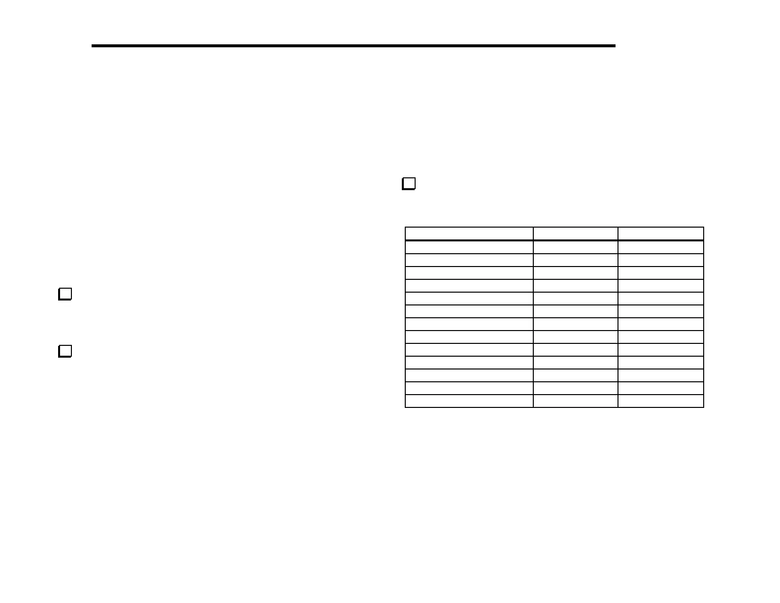
Perform the resistance checks listed below to ensure that there
are no shorts in the most critical control circuits. (The Control
board will be fully tested in a later section.)
Test Point Signal Name Res.
to GND
P2 pin 1 12V > 10 k
U5, OUT ("5V" pin) 5A > 2 k
U4, OUT ("8V" pin) 8A 3 - 7 k
Q1 collector 8 T > 1 M
Q2 collector 8R > 1 M
U3 pin 8 12V IN > 10 k
U6 pin 13 OSC1 > 100 k
U6 pin 14 OSC2 > 100 k
U6 pin 29 DASH 70 - 90 k
U6 pin 30 DOT/PTT 70 - 90 k
U8 pin 2 VPWR > 100 k
U8 pin 15 VBIAS-XFIL > 100 k
U8 pin 16 VBFO > 100 k