ELECRAFT 21
5. Front Panel Board
The Front Panel board includes all of the control and display
devices that you’ll use when operating the K2, including the liquid-
crystal display (LCD), LED bargraph, push-button switches, and
potentiometers. See Appendix D for photos of the completed front
panel assembly.
Components
Open the bag labeled FRONT PANEL and sort the parts into
groups (resistors, diodes, capacitors, etc.). Observe anti-static
precautions when handling ICs and transistors.
Locate the front panel PC board, which is just a bit larger than
the Control board. It is labeled "K2 FP" on the top side, in the
lower right-hand corner.
Assembly
i
Your K2’s appearance and operation will be adversely
affected if the controls or display are not mounted correctly, and in
the indicated sequence. There are also special instructions for
installing components on the bottom of the board.
Locate the Spacer Set PC board (Figure 5-1). Using long-nose
pliers, carefully break out the pushbutton switch spacing tool and
the four backlight LED spacers. Break the material only at the four
indicated points. Note: The switch spacing tool doubles as the PC
board for the RF probe, which will be assembled later.
Figure 5-1
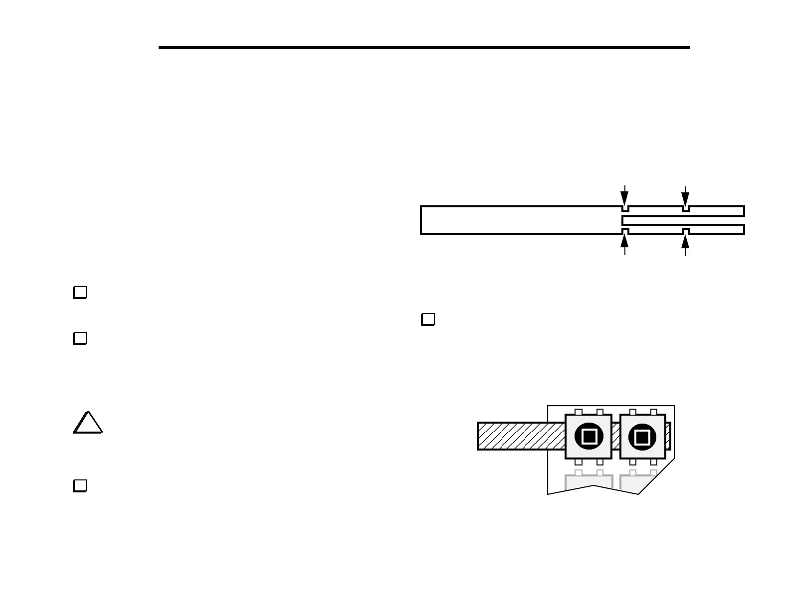
Position pushbutton switches S1 and S2 as shown in Figure 5-2,
using the switch spacing tool to set the switch height. Make sure all
four legs of each switch are centered in their holes, then gently
push each switch until it is resting flush against the switch-spacing
tool. (Caution: switch pins are fragile.) Do not solder yet.
S1 S2
Figure 5-2
SWITCH SPACING TOOL