22 ELECRAFT
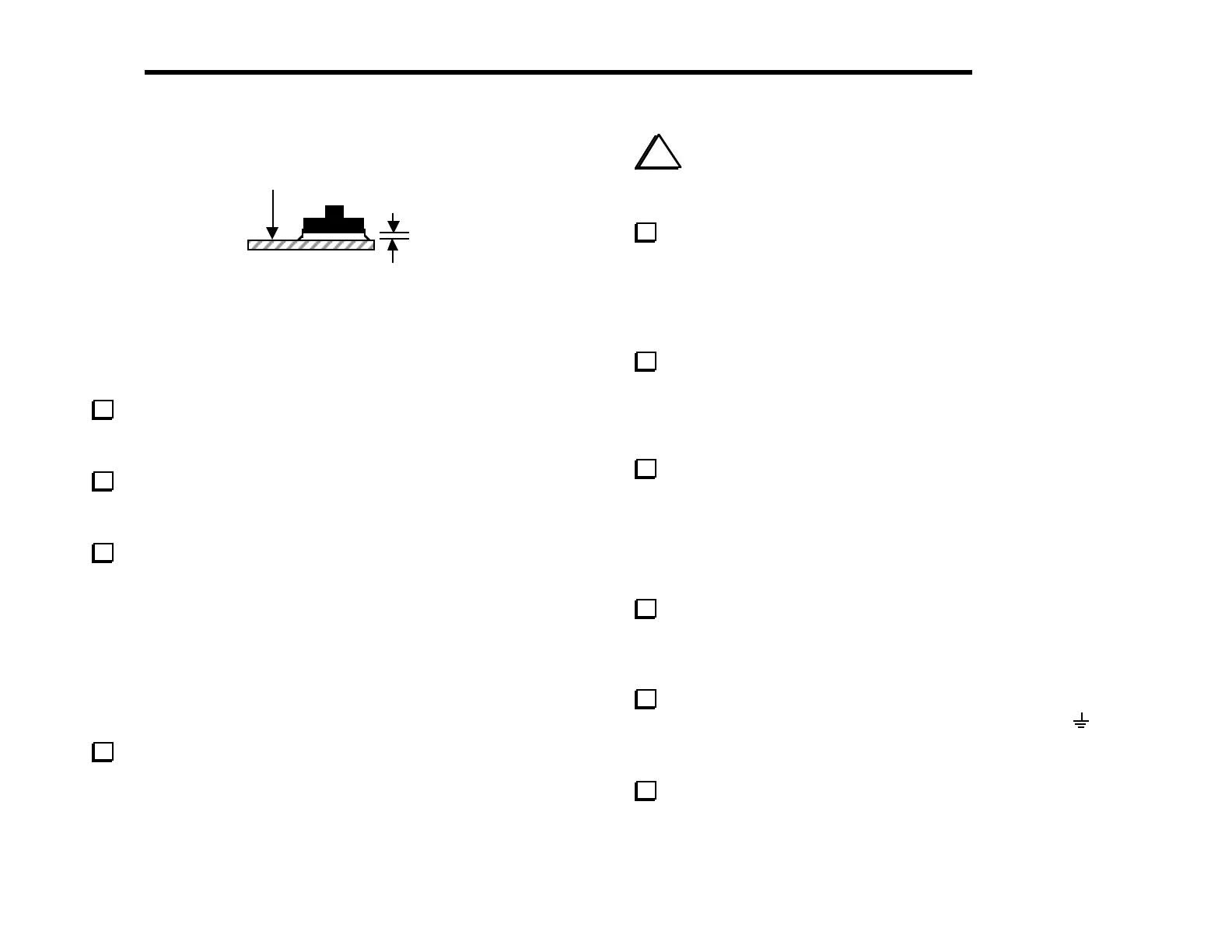
Top of
board
1/16”
Figure 5-3
Figure 5-3 shows a side view of a switch that is properly mounted
(spacing tool not shown). The leads of the switches will just be
visible on the bottom of the board. Proper switch height is
important for maintaining an even appearance.
Once you’re satisfied that S1 and S2 are seated correctly,
solder the leads (on the bottom side of the board). Leave the
spacing tool in place until you’ve finished soldering both switches.
Install the remaining switches, S3-S16, using the same
technique. When you get to S8 through S16, you may install three
switches at a time using the spacing tool.
Install the following 1/4-watt fixed resistors, which are listed
in left-to-right PC board order. Solder the resistors after all have
been installed. (R13 and a few other parts are part of the SSB
adapter option, and are not included in the basic K2 kit. A check-
list of these components is provided at the end of this section.)
__ R12, 120 (BRN-RED-BRN) ⇒ __ R10, 33 (ORG-ORG-BLK)
__ R9, 220 (RED-RED-BRN) __ R11, 470 (YEL-VIO-BRN)
__ R6, 4.7 k (YEL-VIO-RED) __ R7, 4.7 k (YEL-VIO-RED)
__ R14, 100 k (BRN-BLK-YEL)
Install the following resistors on the bottom of the board.
Solder them on the bottom side. Keep your iron tip away from the
bodies of the resistors.
__ R16, 15 k (BRN-GRN-ORG) __ R15, 10 k (BRN-BLK-ORG)
i
When you install the resistor networks in the next
step, you must align the dotted end of the network with the
pin 1 label on the PC board outline.
Install the resistor networks listed below (top side of the
board). Double-check pin 1 orientation and values before soldering.
__ RP2, 120, 10 pins (770101121) (dotted end should be near "RP2" label)
__ RP1, 100 k, 10 pins (10A1.104G) (dotted end near "RP1" label)
Install and solder the diodes listed below, observing proper
orientation as described in the previous section.
__ D4, 1N5817 __ D5, 1N5817 __ D6, 1N5817
Install and solder the following capacitors. C9 is located on the
bottom of the board and must be soldered on the top side.
__ C1, .047 (473) __ C2, .01 (103) __ C3, .047 (473)
__ C9, .01 (103), on bottom
Install PN2222A transistors at Q1 and Q2, near the middle of
the board, and solder. These transistors must be mounted so the lead
length above the PC board is less than 1/8" (3 mm) to prevent
them from hitting the front panel.
There are two ground jumpers on the Front Panel board, one
at the far left and the other at the lower right, labeled with a
symbol. Use discarded component leads to make 3/4" (19 mm) U-
shaped wires for each jumper. Solder them on the bottom side.
Install a 40-pin IC socket at U1, on the bottom of the board.
(The IC will be inserted into this socket later.) Orient the notched
end of the socket to the left as shown on the PC board outline.