24 ELECRAFT
Install another 3/16" (4.8 mm) diameter x 1/4" (6.4 mm) long
round standoff on the top of the PC board, on the left side of the
large square hole in the middle of the board. The standoff mounting
hole is below C2. Use the same hardware as indicated in Figure 5-5,
including two #4 lock washers and one chassis screw.
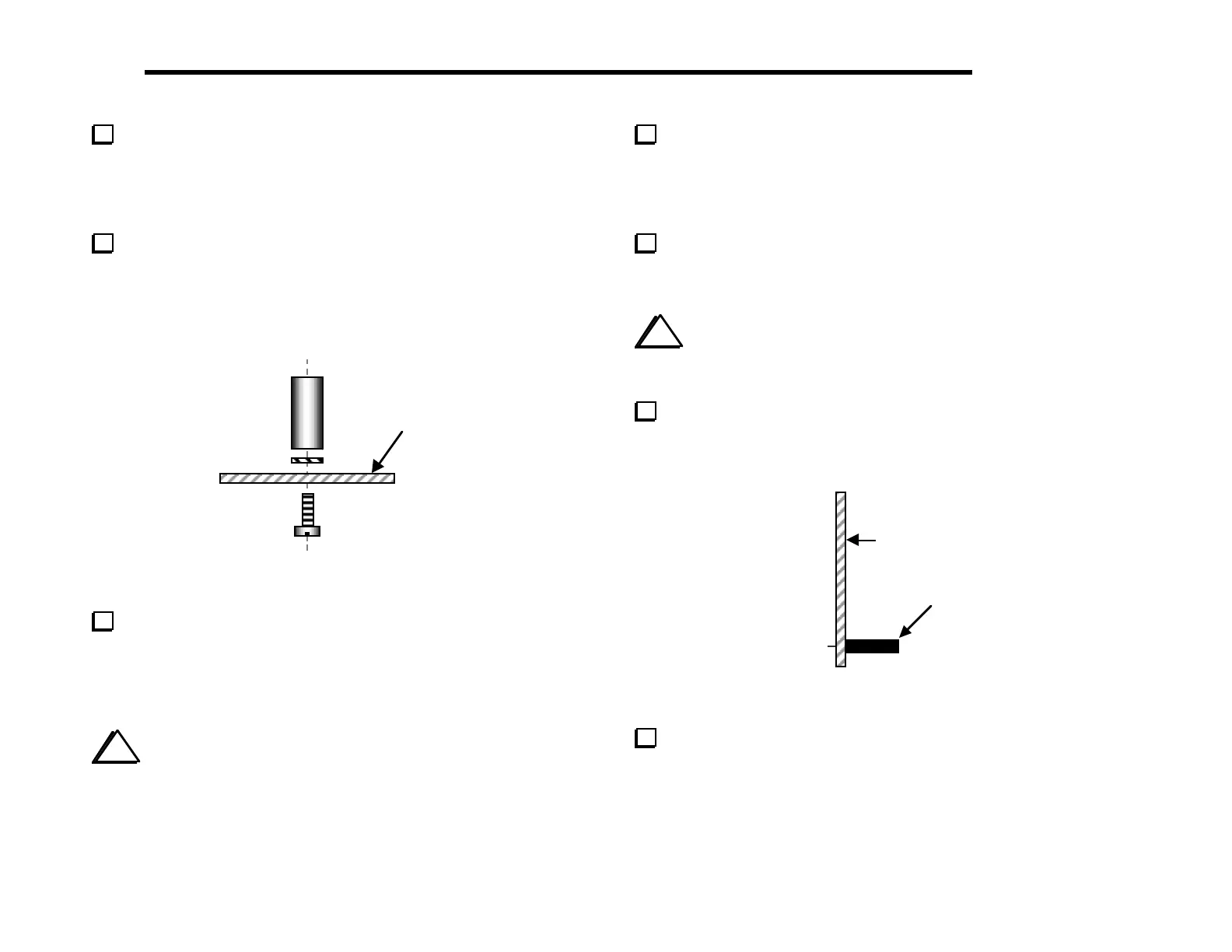
Install two 1/4" (6.4 mm) diameter x 1/2" (12.7 mm) long hex
standoffs on the bottom of the board (Figure 5-6). The holes for
these standoffs are indicated by large pads on the top and bottom of
the board. Use one lock washer and a chassis screw for each
standoff. Insert the lock washer between the standoff and PC board.
Bottom of
PCB
Figure 5-6
Identify the two different types of panel-mount
potentiometers. Four of them are 5-kohm linear-taper types,
labeled "B5K". The fifth is an audio-taper type, labeled "A5K".
They may be physically identical or have slightly different shafts,
body colors, etc.
i
When you install the panel-mount potentiometers
in the next two steps, do not push on the shafts, which may
damage the part. Push only on the metal frame.
Install the audio-taper potentiometer, R3, in the lower left-
hand corner. (The PCB is labeled "AUDIO" at R3.) Push only
on the frame, not the shaft. Make sure that the potentiometer body
is parallel to the PC board and is pressed against the board as far as
it will go before soldering.
Install the four 5-k linear-taper potentiometers at R1, R2, R4,
and R5. (The PC board is labeled "LINEAR" at each pot.) Verify
correct positioning as you did in the previous step.
i
Before installing J1 in the following step, review
Figure 3-3 (page 8) to be sure you have J1 on the correct
side of the board.
The front panel attaches to the RF board via J1, a 20-pin
single-row female connector. Install J1 on the bottom side of
the board (Figure 5-7). Solder just two pins, one at either end.
Bottom side of
PC Board
1
Figure 5-7
Re-heat the two end pins and press the connector down until J1
is seated flat against the board, then solder the remaining pins.