ELECRAFT 25
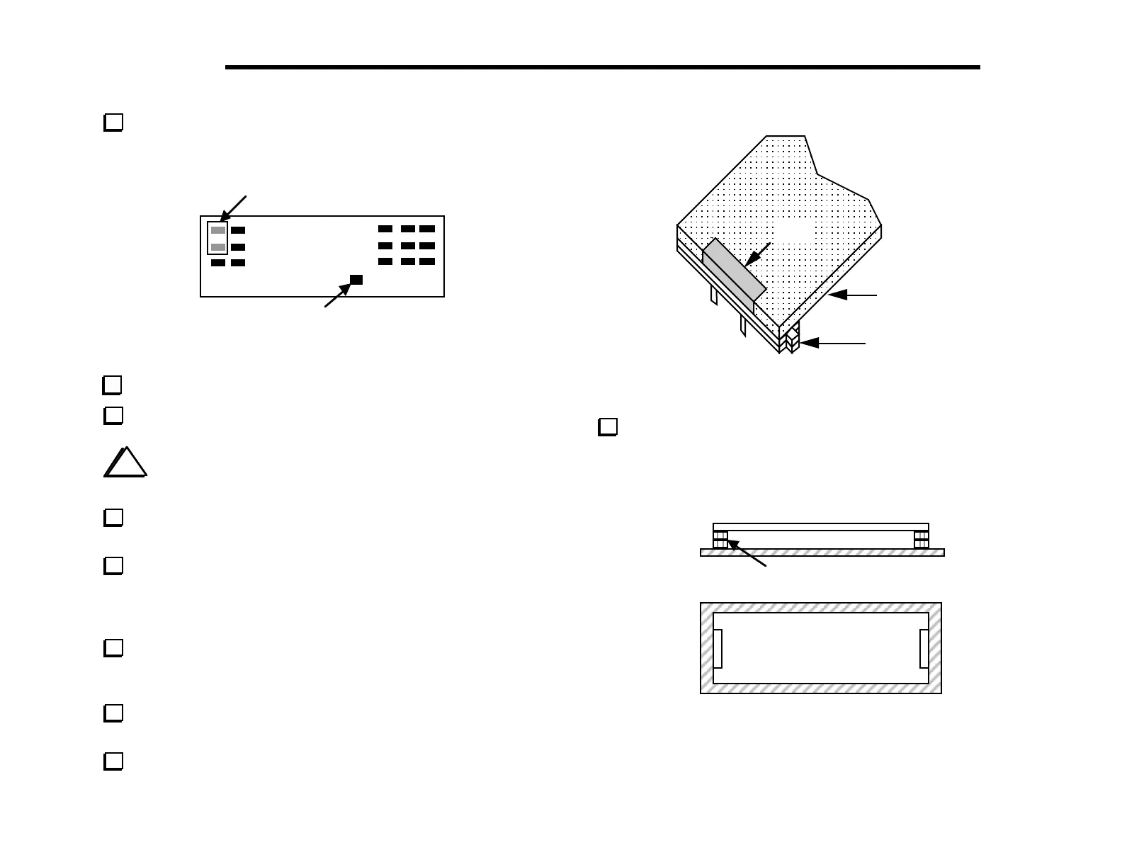
Install rectangular gray key caps on S1 and S3 so the key caps
are parallel to the long axis of the PC board (Figure 5-8). The caps
are installed simply by pressing them onto the switch plungers.
Square Keycap
Gray keycaps
Figure 5-8
Install a square black key cap on S7 as shown above.
Install rectangular black key caps on the remaining switches.
i
Before handling U1, touch an unpainted, grounded
metal surface or put on a conductive wrist-strap.
Straighten the pins of U1, the LCD driver (PCF8566), as you
did with the microcontroller on the Control board.
Insert U1 into its socket on the bottom of the board. (This
must be done before continuing with LCD installation, since the
LCD’s presence will make pressing U1 into its socket much more
difficult.) Be sure that U1 is completely seated with no bent pins.
Locate the LCD backlight assembly, which is about 3" (7.5 cm)
long. It includes the diffuser and two small LEDs, one at each end.
Do not remove the backing from either side of the diffuser.
Make sure the LEDs in the LCD backlight assembly are pressed
into the diffuser and are not mis-aligned or loose.
Place two 3/4" (19 mm) long spacers over the leads of each
backlight LED as shown in Figure 5-9.
spacers (2)
LED
diffuser
Figure 5-9
Position the backlight assembly between the mounting holes
labeled D2 and D3 as shown in Figure 5-10. The diffuser must be
parallel to and 1/8" (3 mm) above the PC board. To hold the LED
spacers and backlight assembly in place, use a rubber band or bend
the LED leads out slightly on either end.
spacers (2)
diffuser
2D3
Figure 5-10