26 ELECRAFT
Examine the backlight assembly closely to ensure that it is
parallel to the Front Panel board and seated as far down on the
board as it will go (exactly 1/8" [3 mm] above the board).
Solder D2 and D3. If the backlight assembly is not flat against
the PC board, re-heat the LED pins one at a time and press it into
place.
i
Caution: The LCD and its pins are fragile—handle
carefully. Do not remove the protective plastic film from the front
surface of the LCD until later in this section when the front panel
assembly is completed.
Remove the LCD from its packing materials, being careful not
to bend the pins.
Look closely at the back surface of the LCD under a bright
light. If you see a few very faint lines running across the back, it
indicates that a piece of protective film is in place. Remove this
piece of film very carefully. (Note: There is also protective film
on the front surface, but do not remove it at this time.)
The LCD has six pins along its lower edge (three on each side),
and 24 pins along the upper edge. Place the LCD in its proper
position on the board but do not solder yet.
CD
Figure 5-11
The LCD must be seated flat against the diffuser as shown in
the edge view (Figure 5-11). If the LCD does not appear to be
seated correctly, it may be because the backlight LEDs or spacers
are mis-aligned. When the entire assembly is installed correctly, the
LCD’s pins will all protrude the same distance from the bottom of
the board. (Some units may be supplied with shorter pins that do
not protrude at all.)
Solder the four corner pins of the LCD, then re-check the
alignment of the LCD assembly. If everything looks correct, solder
the remaining pins. LCD pins can be soldered on the top of the
board if they do not protrude from the bottom.
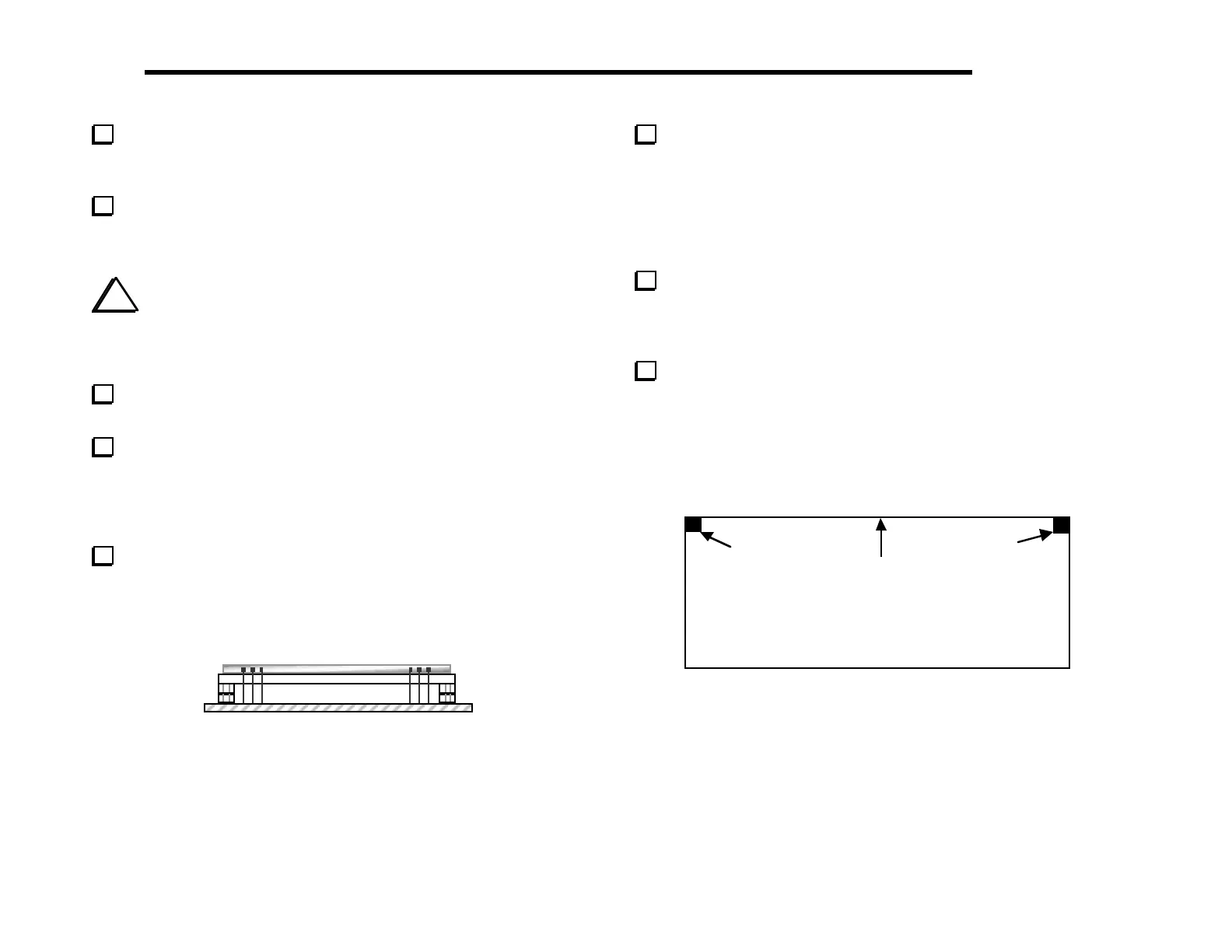
Attach two thin, 1/4" (6.4 mm) self-adhesive rubber pads to
the bottom side of the Front Panel board in the positions indicated
in Figure 5-12. The pads should be placed as close as possible to the
corners, but should not hang over on either edge. These pads
establish the correct spacing for the Front Panel board and provide
some vibration resistance.
(Bottom of PC Board)
Pad
Pad
Top Edge
Figure 5-12