ELECRAFT 31
Attach the encoder to the inside of the front panel using the
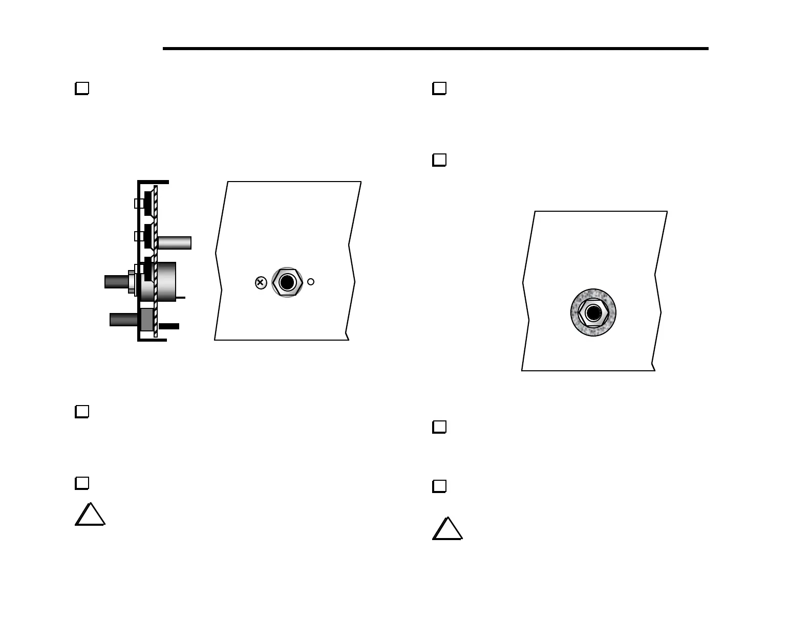
nut and flat washer only. Figure 5-18 shows the side view (a) and
front view (b) with encoder properly installed. The encoder has a
small metal tab near the shaft that will only allow it to be installed
one way. Do not over-tighten the nut. (Note: the green encoder
bushing is metal, not plastic.)
(a)
(b)
Figure 5-18
Attach the four encoder wires you installed earlier to the
matching pins on the back of the encoder. Each wire should be
wrapped securely around the base of its matching pin, with no slack
in the wire. Trim and solder the wires, making sure they aren't
shorting to each other or to the encoder body, which is conductive.
Set all potentiometers to midway in their rotation.
i
In the next step, a small knob may fit too tightly onto its
potentiometer shaft. If so, rotate the shaft until it bumps up against
one of its stops, place the knob at the top of the shaft, and rotate
it slowly in the same direction while gently pressing it down.
Attach small knobs to the potentiometer shafts, starting with
the KEYER and POWER controls. Each knob's two set screws can
be tightened using the small Allen wrench (.050", 1.3 mm). The
knobs should be mounted as close as possible to the panel without
touching it. Align the pointers per panel labeling.
Locate the 1" (25 mm) dia. by 1/16" (1.6 mm) thick felt
washer, and place it over the encoder nut (Figure 5-19). The washer
should be seated on the front panel, with the nut inside it.
Figure 5-19
Place the large knob on the encoder shaft. Push the knob on
until it just touches the felt washer. If the knob does not spin
freely, move it out slightly. If the knob is not contacting the felt
washer at all, it may "drift" slightly once it stops spinning.
Using the larger Allen wrench (5/64", 2 mm), tighten the two
set screws alternately, in small increments.
i
At this point, the pushbutton switches may not all protrude
an equal distance. The switch height will become equalized once the
front panel assembly is mated to the RF board in a later step.