30 ELECRAFT
Remove the insulation from four 1.5" (38 mm) lengths of
green hookup wire.
Install the bare wires on the bottom of the front panel PC
board, using the four pads below the large rectangular hole (Figure
5-16).
Solder and trim the wires on the top side of the board. The
wires will be connected to the optical encoder, Z1, in a later step.
Figure 5-16
Remove the protective plastic film from the face of the LCD.
Be careful not to scratch the glass. Caution: Do not peel off the
LCD glass, just the thin protective film. The LCD will not be
usable if you lift the glass itself.
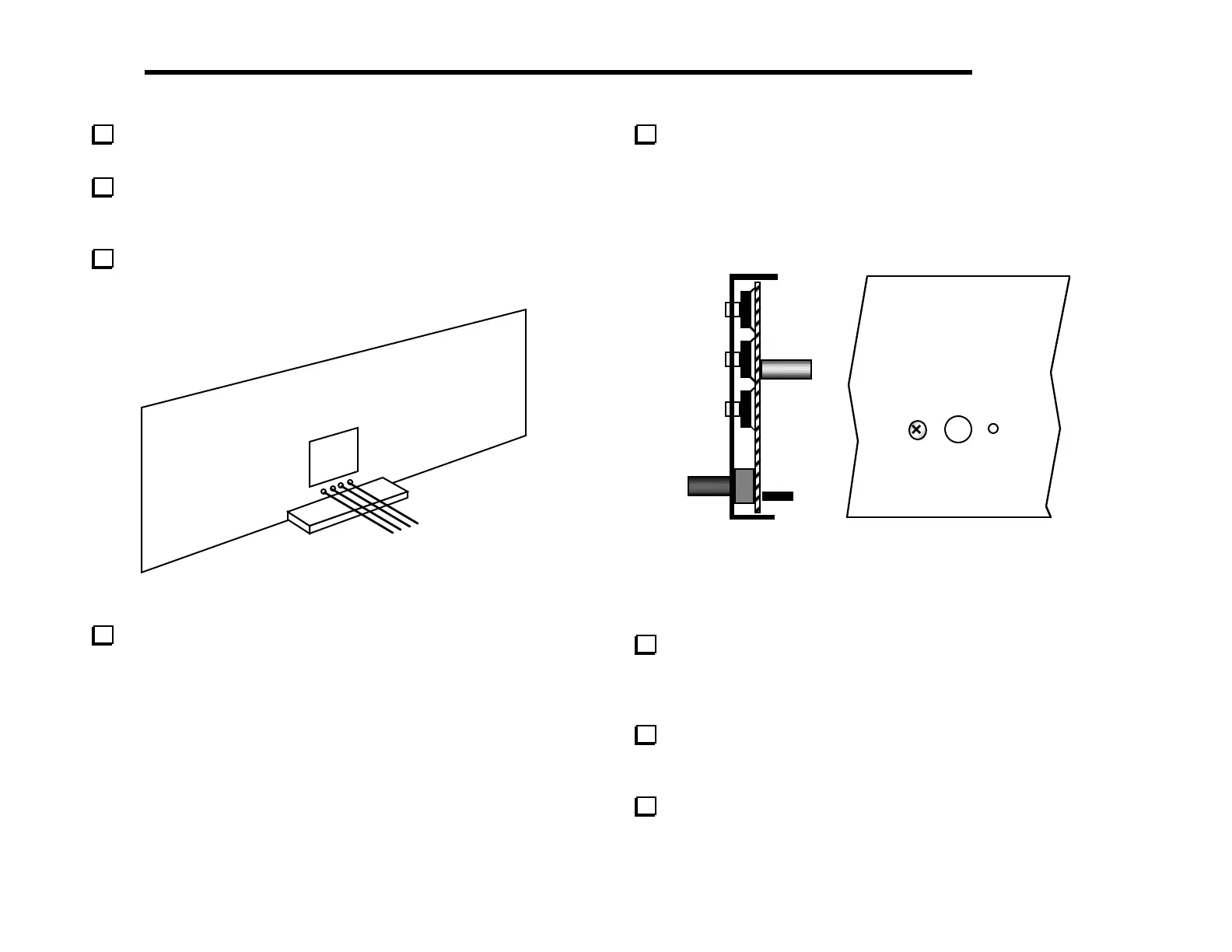
Insert the front panel PC board assembly into the front panel.
The pushbutton switch caps on both sides of the LCD should
protrude slightly as shown in the side view, Figure 5-17a.
Note: the board/panel assembly will not be rigidly held in place
until it is mated with the RF and Control boards in a later section.
(a)
(b)
Figure 5-17
A 1/4" (6.4 mm) standoff on the PC board should now be
visible through the hole just to the left of the encoder mounting
hole. Secure the panel to this standoff using the 4-40 x 3/16"
(4.8 mm) flat-head screw as shown in Figure 5-17b.
Remove the hardware from the shaft of the encoder, Z1, and
discard the lock washer, which will not be used. Insert the encoder
through the hole in the Front Panel board (Figure 5-18a).
Cut 1/8" (3 mm) off the end of each of the encoder's four
connector pins.